Chapter 1, Introduction, Rear panel features – Lanner FW-8895 User Manual
Page 9
5
Introduction
Chapter 1
Network Application Platforms
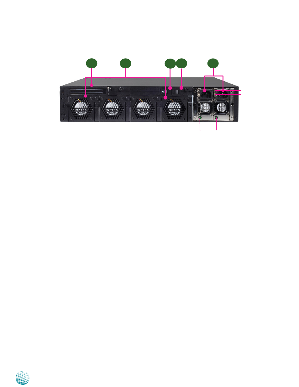
R1 Low Profile Expansion Slot
R2 4 Moduler Fans (Corresponding connectors on the mainboard from left to right: FAN3, FAN2, FAN1, FAN4).
R3 Power-on Switch
It is a switch to turn on or off the power.
R4 Power Supply Alarm Switch
When the alarm sounds (it indicates a power supply failure), switch off this button to turn off the alarm. Replace the failed
power supply as soon as possible.
R5 Redundant Power Supply
The 600W redundant power supply is hot-swappable and can be withdrawn and replaced when the alarm sounds. The
LED of the failed power supply will be turned off. To replace the failed power supply unit, unscrew the screw and press
the latch to release the unit and pull it out.
Rear Panel Features
R3
R1
R2
R5
R4
PSU latch
screw
PSU LED