Chapter 3, Motherboard information, Smart fan mode configuration – Lanner FW-8895 User Manual
Page 18
14
Motherboard Information
Chapter 3
Network Application Platforms
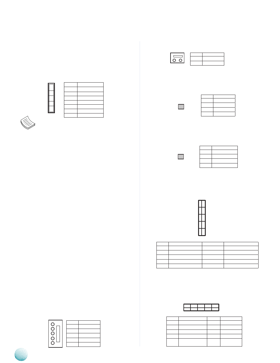
CONN1: Power-on Switch
SW1: on-board power switch for debug.
SW2: An onboard reset button for debug purpose.I
USB1: USB Connector. It is for connecting the USB
module cable. It complies with USB2.0 and support up
to 480 Mbps connection speed.
USB2: USB Connector
3 modes of SATA configuration, i.e., IDE, RAID, and AHCI.
The chipset provides hardware support for Advanced
Host Controller Interface (AHCI) which is a programming
interface for SATA host controllers. AHCI provides advanced
performance and usability enhancements with SATA such
as Hot-Plug, no master/savle designation for SATA devices
and native command queuing (NCQ).
Note:
1.
To configure your Hard disk using the
integrated RAID feature, the Intel®Rapid
Storage Technology Utility has to be installed
on your Operating System.
2.
You will need to select the RAID mode in the
BIOS for your SATA drives first. There is also a
Intel® RSTe OpROM utility for creating RAID
volume; to enter the RSTe OpROM, press Ctrl-I
during POST.
3.
For operating systems other than Microsoft®
Windows Vista and Windows® 7, it is
required to pre-install the Intel Rapid Storage
Technology driver during the F6 installation of
Windows setup (“press F6 if you need to install
a third party SCSI or RAID driver....”).
Visit the Intel support page at http://www.intel.
com/p/en_US/support/highlights/chpsts/imsm
for more information and download links.
4.
The Intel controller hubs are also supported
by Linux. Beginning with Linux kernel
version 2.6.27, the mdadm utility 3.0
supports RAID 0, RAID 1, RAID 5, and RAID
10. To use the RAID features in dmraid and
mdadm, you will need to set up the RAID
volume using the Intel® Matrix Storage
Manager option ROM (click CTRL + I when
prompted during boot to enter the option
ROM user interface).
FAN1~4: 5-Pin FAN Connector. The 4-pin connector
is for connecting the CPU and system fans. These fans
have smart features that which can are automatically set
to operate at certain speed according to the deteced CPU
or system temperatures. For more information, see
Smart
Fan Mode Configuration
on Chapter 4 BIOS Settings.
Pin No.
Description
1
Ground
2
12V
3
RPM Sense
4
RPM Sense
5
PWM Status
10
8
6
4
2
9
7
5
3
1
5
4
3
2
1
2 1
4 3
Pin No.
Description
1
Ground
2
Ground
3
FP_SWIN_R
4
FP_SWIN_R
1 3
2 4
Pin No.
Description
1
Ground
2
Ground
3
FP_RST_SEL
4
FP_RST_SEL
9 7 5 3 1
1 0 8 6 4 2
Pin No.
Description
Pin No.
Description
1
USB_VCC
2
USB_VCC
3
USBD2-
4
USBD3-
5
USBD2+
6
USBD3+
7
Ground
8
Ground
9
USB
Port#3Ground
10
USB Port#4
Ground
Pin No.
Description
Pin No.
Description
1
USB_VCC
2
USB_VCC
3
USBD0-
4
USBD1-
5
USBD0+
6
USBD1+
7
Ground
8
Ground
9
USB Port#1Ground
10
USB Port#2 Ground
7
6
5
1
Pin No.
Function
1
GND
2
TX_P
3
TX_M
4
GND
5
RX_M
6
RX_P
7
GND
2 1
Pin No.
Description
1
Ground
2
FP_SWIN_R