Chapter 3, Chapter 3: board layout, Board layout – Lanner LEC-2280 User Manual
Page 10: Connectors
Advertising
10
Board Layout
Chapter 3
Embedded and Industrial Computing
Chapter 3:
Board Layout
Connectors
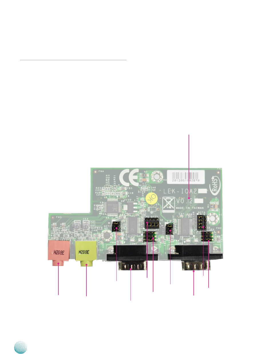
The following picture highlights the location of the COM
port and audio expansion card. Refer to the table 3.1
Connector List for more details.
Note: Daughter boards such as COM ports and
low-profile PCIe extension boards can only be
inserted to the mainboards with the same version.
Failure to do so may damage the system. The
board version is shown on top of the boards.
COM1
COM2
CN1
CN2
sCT2
sCT1
JP1
sCT4
sCT3
JP2
LEK-IOA2
Board Version
Advertising
See also other documents in the category Lanner Computer hardware:
- LVC-2000 (39 pages)
- LVC-5000(N4) (42 pages)
- LVC-5550S (41 pages)
- LVC-5570 (48 pages)
- LVC-5770 (49 pages)
- FW-6432 (16 pages)
- FW-7525 (41 pages)
- FW-5330 (38 pages)
- FW-6486 (18 pages)
- FW-6436 (19 pages)
- FW-7573 (44 pages)
- FW-7568 (52 pages)
- FW-7540 (47 pages)
- FW-8759 (47 pages)
- FW-7581 (23 pages)
- FW-8758 (42 pages)
- FW-7610 (44 pages)
- FW-8756 (24 pages)
- FW-7575 (48 pages)
- FW-8760 (53 pages)
- FW-8877 (46 pages)
- FW-8892 (58 pages)
- FW-8893C (49 pages)
- FX-3411 (48 pages)
- FW-8894 (31 pages)
- FW-8771 (47 pages)
- RS12-38800 (64 pages)
- MR-320 (20 pages)
- FX-3210 (54 pages)
- MR-301 (16 pages)
- MR-350 (12 pages)
- MR-330A (16 pages)
- MR-730 (18 pages)
- VES-220 (19 pages)
- VES-270 (19 pages)
- VES-310 (15 pages)
- VES-310 V2 (20 pages)
- VES-500 (21 pages)
- EM-F345 (30 pages)
- VES-8X2 (16 pages)
- VES-8X6 (17 pages)
- LEC-2026 (67 pages)
- LEC-2010 (65 pages)
- LEC-2136 (20 pages)
- LEC-2050 (38 pages)