Chapter 3, Board layout, Jumper settings – Lanner LEC-2280 User Manual
Page 15: Sct1, Sct3, Sct4
15
Board Layout
Chapter 3
Embedded and Industrial Computing
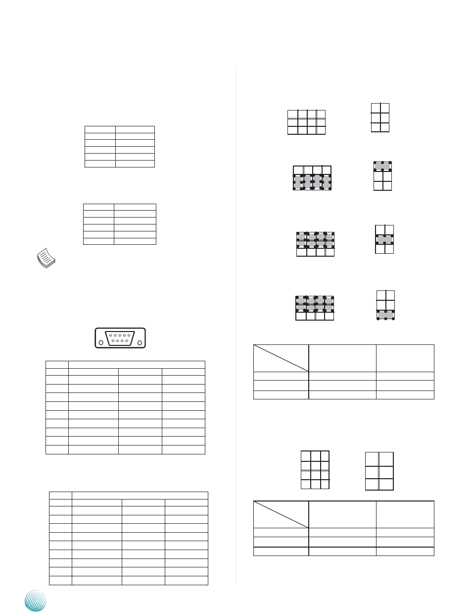
SCT1, SCT2: Select COM1 Protocol Setting
RS-232
RS-422
RS-485
Switch
Protocol
SCT1
SCT2
RS-232 (default)
1-5, 2-6, 3-7, 4-8
1-2
RS-422
5-9, 6-10, 7-11, 8-12
3-4
RS-485
5-9, 6-10, 7-11, 8-12
5-6
SCT3, SCT4: Select COM2 Protocol Setting
Switch
Protocol
SCT3
SCT4
RS-232 (default)
1-5, 2-6, 3-7, 4-8
1-2
RS-422
5-9, 6-10, 7-11, 8-12
3-4
RS-485
5-9, 6-10, 7-11, 8-12
5-6
Jumper Settings
Microphone-in Audio Jack (CN1)
Line-out Audio Jack (CN2)
Note: The driver for the VGA and Audio ports
should be installed with the following order:
Chipset INF->Graphic->Audio
COM1 RS-232 Serial Port(COM1): It is a RS-232/422/485
port through the D-SUB9 connector.
RS-232/422/485 Serial Port(COM2): It is a RS-232/422/485
port through the D-SUB9 connector.
6 7 8 9
1 2 3 4 5
Pin No.
Function
1
CO_GNd
2
MIC_INL
3
CO_GNd
4
INsULATOR
5
MIC_INR
LEK-IOA2 Board
Pin No.
Pin Name
Rs-232
Rs-422
Rs-485
1
dCd
TXd-
dATA-
2
RXd
TXd+
dATA+
3
TXd
RXd+
4
dTR
RXd-
5
GNd
6
dsR
7
RTs
8
CTs
9
RI
Pin No.
Function
1
CO_GNd
2
LINOUT-L
3
CO_GNd
4
INsULATOR
5
LINOUT- R
Pin No.
Pin Name
Rs-232
Rs-422
Rs-485
1
dCd
TXd-
dATA-
2
RXd
TXd+
dATA+
3
TXd
RXd+
4
dTR
RXd-
5
GNd
6
dsR
7
RTs
8
CTs
9
RI
SCT2
1
3
5
2
4
6
SCT1
9
5
1
12
8
4
9
5
1
12
8
4
1
3
5
2
4
6
1
3
5
2
4
6
1
3
5
2
4
6
9
5
1
12
8
4
9
5
1
12
8
4
SCT3
1
2
3
4
9
10
11
12
SCT4
1
3
5
2
4
6