Chapter 3, Board layout, Connectors and jumpers list – Lanner LEC-2280 User Manual
Page 14
14
Board Layout
Chapter 3
Embedded and Industrial Computing
Connectors and Jumpers List
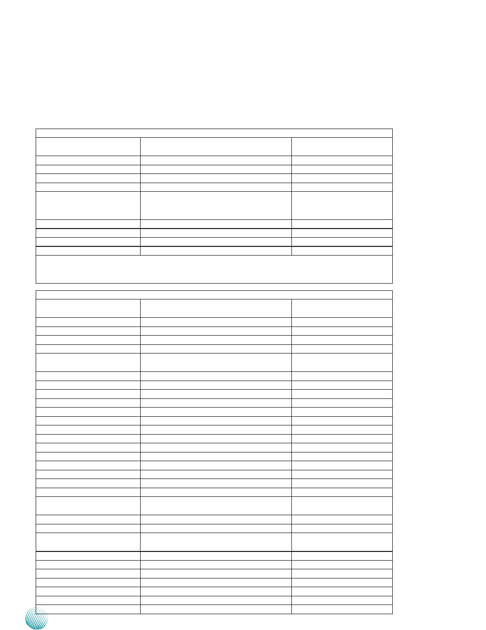
The tables below list the function of each of the board
jumpers and connectors by labels shown in the above
section. The next section in this chapter gives pin
definitions and instructions on setting jumpers.
Table 3.1 Connector List for LEK-IOA2 Board
Labels
Function
Pin Definition Reference
Page
CN1
Microphone-in Audio Jack
P15
CN2
Line-out Audio Jack
P15
COM1
RS232/422/485 Serial Port
P15
COM2
RS232/422/485 Serial Port
P15
MIO1
Connector for connecting the COM port and
audio expansion board to the LEC-2280 main
board
P16
SCT1/SCT2
Select COM1 Protocol Setting
P15
SCT3/SCT4
Select COM2 Protocol Setting
P15
JP1
Select COM1 Pin No. 9 function
P16
JP2
Select COM2 Pin No. 9 function
P16
Note: Daughter boards such as COM ports and low-profile PCIe extension boards can only be inserted
to the mainboards that has the same version as the extension boards. The board version is shown on
top of the boards. Failure to do so may damage the system.
Table 3.2 Connector List for LEB-2280 Board
Labels
Function
Pin Definition Reference
Page
CMOS1
Cleaning CMOS data including RTC
P16
CMOS2
Cleaning CMOS data only
P16
COMSLT1
Daughter board LEK-IOA3 enable/disable
P20
COMSLT2
Daughter board LEK-IG1 enable/disable
P20
CN3 (optional)
Optional Power Connector with Power
-ignition Control
P20
CN4
DC-in Power Connector
P19
DCJK1 (optional)
Optional DC Jack type of Power Connector
P20
DVID1
DVI-D Connector
P18
FAN1/FAN2
System Fan Connector
P18
Front1
Front Panel Function Pin Header
P17
HDMI1
HDMI Port
P18
Ignition1(optional)
Connector for power Ignition Control
P20
J1
PEG16X Lane Function Selection
P19
LAN1/LAN2
Ethernet Connector 1/Ethernet Connector 2 P20
LPC1
Low Pin Count Interface
Reserved for factory use
KBM1
Keyboard and Mouse Connector
P20
MIO1
COM and Audio Expansion Card Connector
P17
MPCIE1
Mini-PCIe Connector
P19
MPCIE2
Mini-PCIe Connector
P19
PCIEIO1
PCI/PCIE Expansion connector for PCI or PCIe
low profile card (PCIEIO1, on the backside)
P18
PWR1
Right-angled SATA Power Connector
P17
RST1
Reset Button
P19
SATA1/SATA2
Serial-ATA Connector (SATA2 supports SATA-
DOM)
P16
SATA_PW2
Switch for SATA port 2 power state
P21
SATA_PWR1
SATA Power Connector
P17
SIM1
SIM Card Reader
P17
SPI1
Serial Peripheral Interface Bus
Reserved for factory use
USB1/USB2/USB3
USB Type A Connector #0,1; #2,3; #4,5
P17
USB4
USB Pin Header
P17
VGA1
VGA Port
P18