Gpio configuration, Baud rate, Using the low power features – Linx Technologies HUM-xxx-DT User Manual
Page 12: External amplifier control
– –
– –
18
19
Using the Low Power Features
The module supports several low-power features to save current in battery
powered applications. Only EDs can use the low power states. APs and
REs must be fully powered.
Taking the Power Down (POWER_DOWN) line low places the module into
the lowest power state. In this mode, the internal voltage regulator and all
oscillators are turned off. All circuits powered from voltage regulator are
also off. All GPIO lines retain the mode and output value set before entering
power down. The module is not functional while in this mode and current
consumption drops to about 0.3µA. Taking the line high wakes the module.
In Sleep, only the radio is powered down while all of the processor
functions are still active. This has higher current consumption than power
down, but leaves the processor able to perform functions, such as
monitoring the GPIO lines. This state is controlled by a serial command.
In Idle, the receiver is disabled while processor is still running. The module
switches to transmit mode when it has data to send. This state is controlled
by a serial command.
External Amplifier Control
The HumDT
TM
Series transceiver has two output lines that are designed
to control external amplifiers. The PA_EN line goes high when the module
enters transmit mode. This can be used to activate an external power
amplifier to boost the signal strength of the transmitter. The LNA_EN line
goes high when the module enters receive mode. This can be used to
activate an external low noise amplifier to boost the receiver sensitivity.
These external amplifiers can significantly increase the range of the system
at the expense of higher current consumption and system cost.
GPIO Configuration
The module has 8 General Purpose Input / Output lines that can be
configured and controlled through the Command Data Interface. They can
be set in one of three ways.
• Digital Input - can be queried to see if the line is logical high or low.
• Digital Output - can be set to either logical high or low.
• Analog Input - connected to an internal Analog to Digital Converter
(ADC). This provides a digital number that is proportional to the voltage
on the line referenced to V
CC
(0V to VCC range, 12 bits resolution).
Digital input lines have an internal pull-up to V
CC
of approximately 20kOhm
by default. The digital inputs can be configured to have either pull up or pull
down resistors or be tri-state to fit different user hardware implementations.
Please see the Command Data Interface section for details on how to
configure the GPIO settings.
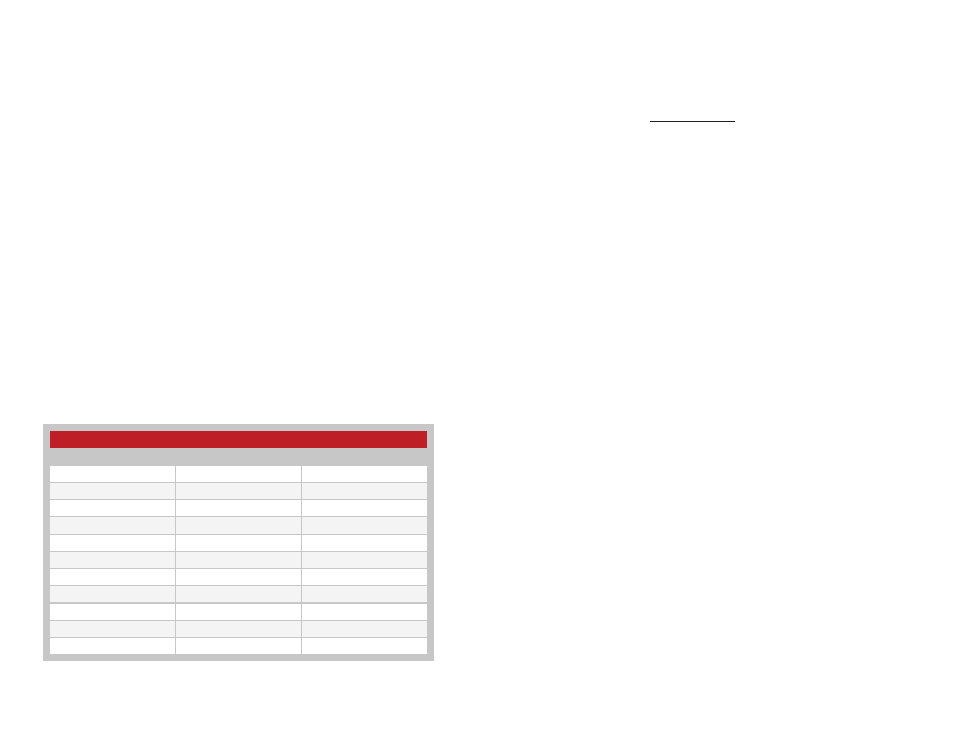
Baud Rate
The module supports multiple serial baud rates on the UART for the
Command Data Interface. The module uses the serial rate that is selected
to automatically select one of its four RF baud bands. These baud bands
determine the internal filter settings and the over-the-air data rate. Figure 18
shows the serial baud rate and the resulting baud band and RF baud rate.
Baud Rate Configuration
Serial Baud Rate (kbps)
RF Baud Band
RF Baud Rate (kbps)
1.2
0
26
2.4
0
26
4.8
0
26
9.6
0
26
14.4
1
80
19.2
1
80
28.8
1
80
38.4
1
80
57.6
2
250
115.2
2
250
reserved
3
500
Figure 18: Baud Rate Configuration