The command data interface command set, Send data packet – Linx Technologies HUM-xxx-DT User Manual
Page 15
– –
– –
24
25
The Command Data Interface Command Set
The following sections describe the commands and parameters.
The module has two forms of memory, volatile and non-volatile. Volatile
memory is temporary and all values are lost when power is removed from
the module. However, it is faster to access and the module typically uses
the values in volatile memory during operation.
Non-volatile memory is retained when power is removed from the module.
This is where default values are stored. When the module powers on, it
pulls some values from non-volatile memory and loads them into volatile
memory for use during normal operation.
There is one command to read (Command Code = 22) and one command
to write (Command Code = 23) all of the configurations in non-volatile
memory. The non-volatile memory has a life expectancy of about 1,000
writes, so using one command for all settings helps extend the life time.
Volatile settings have separate commands for each setting since it has
a much larger life expectancy. This makes it easier to change just one
configuration value.
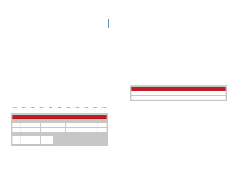
Send Data Packet - Command Code = 21
This command instructs the module to transmit a data packet over the air.
The first four bytes consist of the destination address for the data packet
with the DestAdr3 (Param 1 byte) being the Most Significant Byte (MSB).
The Len byte (Param 5) is the total number of bytes in the Parameter and
Data fields (5 bytes plus the number of data bytes).
Send Data Packet Command and Response
Command
Start
Cmd
Param 1
Param 2
Param 3
Param 4
Param 5
Data
End
3C
21
DestAdr3 DestAdr2 DestAdr1 DestAdr0
LEN
DATA
3E
Response
Start
Rsp
Param1
End
3C
21
Status
3E
Figure 21: Send Data Packet Command and Response
The Data field contains 0 to 32 bytes of user defined data.
The response parameter indicates if the module successfully processed
the command (0x00) or if there was an error (0x01). It only indicates that
the data packet has been successfully transmitted by module. It does not
indicate that the data was successfully received by the remote device.
When data is received by the module, the output format follows the
same format with two exceptions. The source address (address of the
transmitting module) replaces the destination address and the module adds
one or two RSSI bytes to the end of the response.
The RSSI values depend on the number of hops the packet took. From AP
to ED is one hop and only one RSSI byte is added. Transmissions from one
ED to another ED must go through the AP, so there are two hops. RSSI1 is
the first hop, RSSI2 is the second hop. There is no placeholder, so RSSI2 is
either there or not.
The LEN byte includes the Parameter, Data and RSSI bytes.
The RSSI value is returned in 2’s complement hex format. The RSSI value
in dBm can be calculated based on the formula shown below.
RSSI (dBm) = RSSI_value (in the response) - 256
Received Data Packet Output
Start Cmd Param 1 Param 2 Param 3 Param 4 Param 5 Data RSSI1 RSSI2 End
3C
20 SrcAdr3 SrcAdr2 SrcAdr1 SrcAdr0
LEN
DATA RSSI1 RSSI2 3E
Figure 22: Received Data Packet CDI Output
Note:
All values are shown in hexadecimal format unless otherwise
stated.