Theory of operation, Module description – Linx Technologies HUM-xxx-DT User Manual
Page 9
– –
– –
12
13
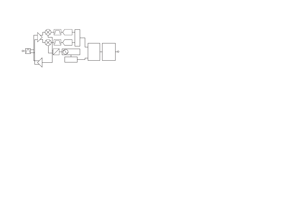
Theory of Operation
The HumDT
TM
Series transceiver is a low-cost, high-performance
synthesized MSK transceiver. Figure 15 shows the module’s block diagram.
The HumDT
TM
Series transceiver operates in the 863 to 870MHz and
902 to 928MHz frequency bands. The transmitter output power is
programmable. The range varies depending on the module’s frequency
band, antenna implementation and the local RF environment.
The RF carrier is generated directly by a frequency synthesizer that includes
an on-chip VCO. The received RF signal is amplified by a low noise
amplifier (LNA) and down-converted to I/Q quadrature signals. The I/Q
signals are digitized by ADCs.
A low-power onboard communications processor performs the radio
control and management functions including Automatic Gain Control
(AGC), filtering, demodulation and packet synchronization. A control
processor performs the higher level functions and controls the serial and
hardware interfaces.
A crystal oscillator generates the reference frequency for the synthesizer
and clocks for the ADCs and the processor.
PA
LNA
0
90
FREQ
SYNTH
ADC
ADC
DEMODULATO
R
MODULATOR
ANTENNA
PROCESSOR
GPIO /
INTERFACE
INTERFACE
Figure 15: HumDT
TM
Series Transceiver RF Section Block Diagram
Module Description
The HumDT
TM
Series module is a completely integrated RF transceiver
and processor designed to transmit digital data across a wireless link. It
has a built-in frequency agile over-the-air protocol that manages all of the
transmission and reception functions. It takes data in on its UART and
supplies the data out of a UART on the remote module.
The frequency agile protocol transmits the same data packet on 1 to 4
channels. The user can select how many channels are used and which of
the four available channels are active. This method provides some of the
noise immunity offered by frequency hopping systems, but without all of the
overhead and latency required by the hopping algorithm.
The modules can be used to set up a star network with one module acting
as the central hub or access point and up to 50 other modules as end
nodes connected to the hub. The module supports one-hop routing so that
the end nodes can communicate with each other through the access point.
The network can also support up to four range extenders that can boost
the physical size of the network.
Each module has 8 GPIOs that can be configured as digital inputs or
outputs or as analog inputs. These are controlled through serial commands
used by the module’s Command Data Interface through a UART. These
can act as a GPIO expander or as sensor voltage inputs.
A standard UART interface is used to configure the module for operation
and for the data input and output. This is suitable for direct connection to
UARTs on many microcontrollers, USB converters and RS-232 converters.
A simple command set is used for configuration and data input.