Theory of operation, Module description – Linx Technologies TRM-xxx-TT User Manual
Page 10
– –
– –
14
15
Theory of Operation
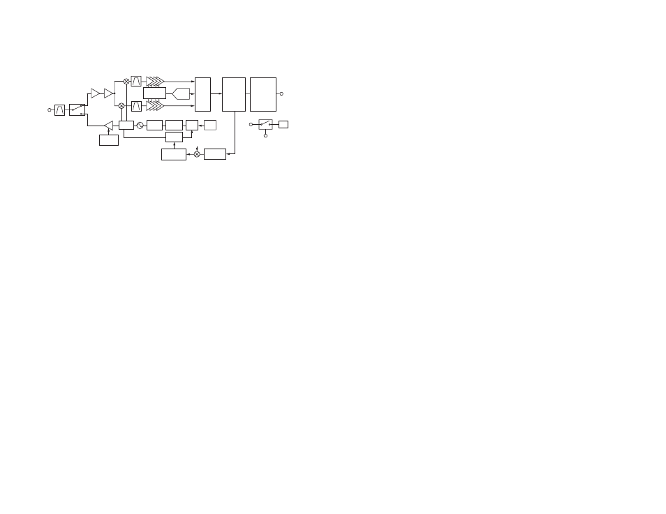
The TT Series transceiver is a low-cost, high-performance synthesized
FSK transceiver. Its exceptional sensitivity results in outstanding range
performance. Figure 20 shows a block diagram for the module.
The TT Series transceiver is designed for operation in the 902 to 928MHz
frequency band. The RF synthesizer contains a VCO and a low-noise
fractional-N PLL. The VCO operates at twice the fundamental frequency
to reduce spurious emissions. The receive and transmit synthesizers
are integrated, enabling them to be automatically configured to achieve
optimum phase noise, modulation quality and settling time.
The transmitter output power is programmable from −15.5dBm to
+12.5dBm with automatic PA ramping to meet transient spurious
specifications. The ramping and frequency deviation are optimized to
deliver the highest performance over a wide range of data rates.
The receiver incorporates highly efficient low-noise amplifiers that provide
up to –112dBm sensitivity. Advanced interference blocking makes the
transceiver extremely robust when in the presence of interference.
A low-power onboard communications processor performs the radio
control and management functions. A control processor performs the
higher level functions and controls the serial and hardware interfaces.
This block also includes voltage translation to allow the internal circuits to
operate at a low voltage to conserve power while enabling the interface to
operate over the full external voltage. This prevents hardware damage and
communication errors due to voltage level differences.
While operation is recommended from 3.3V to 5.0V, the transceiver can
operate down to 2.5V.
RSSI/
LOGAMP
LNA
FSK
DEMOD
CDR
AFC
AGC
PROCESSOR
26MHz
OSC
PA RAMP
PROFILE
PA
8-BIT
ADC
LOOP
FILTER
CHARGE
PUMP
PFD
DIVIDER
Σ-Δ
MODULATOR
GAUSSIAN
FILTER
f
DEV
DIVIDER
LNA
ANTENNA
GPIO /
INTERFACE
LDO
VCC
PDN
INTERFACE /
VOLTAGE
TRANSLATION
Figure 20: TT Series Transceiver RF Section Block Diagram
Module Description
The TT Series remote control and sensor transceiver module is a
completely integrated RF transceiver and processor. It has two main
modes of operation: hardware and software. Hardware operation is basic
and is suitable for applications like keyfobs where no other processor, PC
or interface is present. Software operation is more advanced and allows for
more features and functionality. This guide focuses on hardware operation
with some references to software operation. Please see Reference Guide
RG-00103: the TT Series Command Data Interface for details on software
operation.
The module has 8 status lines numbered S0 through S7. These can be set
as inputs for buttons or contacts or as outputs to drive application circuitry.
When S0 is taken high on one module S0 goes high on the receiving
module, and so forth. A line that is an input on one side needs to be set as
an output on the other side.
Since this module can act as both transmitter and receiver, terminology and
descriptions are important. This guide uses the term Initiating Unit (IU) to
describe a module that is transmitting commands. Responding Unit (RU) is
used to describe a module that is receiving commands.
The transceiver uses a Frequency Hopping Spread Spectrum (FHSS)
algorithm. This allows for higher output power and longer range than
narrow-band systems while still maintaining regulatory compliance. All
aspects of managing the FHSS operations are automatically handled by the
module.
The TT Series has received modular certification for the FCC in the United
States and Industry Canada when used with an approved antenna. The
module may be placed in an end product without further transmitter
testing, though unintentional radiator testing may be required. Please see
the Usage Guidelines for FCC Compliance section for more details.