Receiver duty cycle, Power supply requirements – Linx Technologies TRM-xxx-TT User Manual
Page 16
– –
– –
26
27
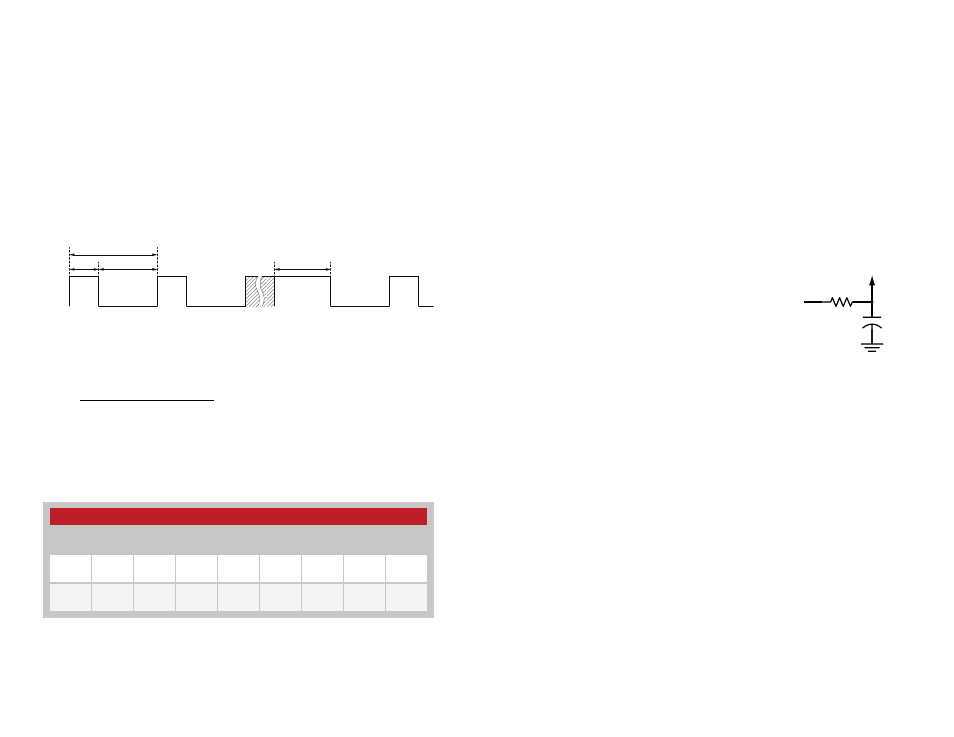
Receiver Duty Cycle
The module can be configured to automatically power on and off while
in receive mode. Instead of being powered on all the time looking for
transmissions from an IU, the receiver can wake up, look for data and go
back to sleep for a configurable amount of time. If it wakes up and receives
valid data, then it stays on and goes back to sleep when the data stops.
This significantly reduces the amount of current consumed by the receiver.
It also increases the time from activating the IU to getting a response from
the RU.
The duty cycle is controlled by the Duty Cycle serial command through the
Command Data Interface. DCycle sets the number of seconds between
receiver turn on points as shown in Figure 24.
The module’s average current consumption can be calculated with the
following equation.
T
ON
is fixed at about 0.326 seconds and T
SBY
= DCycle - T
ON
. The receiver
current (I
RX
) and standby current (I
SBY
) vary with supply voltage, but some
typical values are in Figure 26.
Figure 15 shows a graph of the average current consumption vs. duty cycle
for several supply voltages. This graph shows that the average current
consumption can be significantly reduced with even a small duty cycle
value. This is ideal for battery-powered applications that need infrequent
updates or where response time is not critical.
The KeepOn time is used to keep the receiver on after it has completed
some activity. This activity includes completing a transmission and receiving
a valid packet. After KeepOn seconds have elapsed with no transmit or
valid receive activity, the module goes into standby for DCycle seconds.
Please see Reference Guide RG-00103: the TT Series Command Data
Interface for details on configuring the receiver duty cycle.
Power Supply Requirements
The transceiver incorporates a precision
low-dropout regulator which allows operation
over a wide input voltage range. Despite this
regulator, it is still important to provide a supply
that is free of noise. Power supply noise can
significantly affect the module’s performance, so
providing a clean power supply for the module
should be a high priority during design.
A 10
Ω resistor in series with the supply followed by a 10µF tantalum
capacitor from V
cc
to ground helps in cases where the quality of supply
power is poor (Figure 27). This filter should be placed close to the module’s
supply lines. These values may need to be adjusted depending on the
noise present on the supply line.
+
10
Ω
10
µF
Vcc IN
Vcc TO
MODULE
Figure 27: Supply Filter
DCycle
T
ON
KeepOn
Activity
ON
Standby
T
SBY
I
T
I
T
I
DCycle
AVG
ON
RX
SBY
SBY
=
×
(
)
+
×
(
)
Figure 24: Receiver Duty Cycle
Figure 25: Receiver Duty Cycle Average Current Consumption Equation
TT Series Typical Current Consumption
V
CC
(VDC)
2.5
3.0
3.3
3.5
4.0
4.5
5.0
5.5
I
RX
(mA)
16.5
17.8
18.7
18.8
18.8
18.9
18.9
18.9
I
SBY
(mA)
0.0862
0.1471
0.1509
0.1525
0.1569
0.1616
0.1669
0.1737
Figure 26: TT Series Transceiver Typical Current Consumption