Frequency hopping – Linx Technologies TRM-xxx-TT User Manual
Page 18
– –
– –
30
31
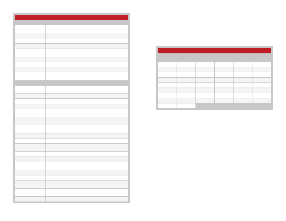
Command Data Interface Commands and Parameters
Command
Description
Read
Read the current value in volatile memory. If there is no volatile
value, then the non-volatile value is returned.
Write
Write a new value to volatile memory.
Read NV
Read the value in non-volatile memory.
Program
Program a new value to non-volatile memory.
Set Default
Configuration
Set all configuration items to their factory default values.
Erase All Addresses
Erase all paired addresses from memory.
Transmit Control Data
Transmit a control message.
Transmit ACK
Transmit an acknowledgement for received data.
Transmit AWD
Transmit an Acknowledge With Data (AWD) response with two
bytes of custom data.
Parameter
Description
Device Name
NULL-terminated string of up to 16 characters that identifies the
module. Read only.
Firmware Version
3 byte firmware version. Read only.
Serial Number
4 byte factory-set serial number. Read only.
Local Address
The module’s 32-bit local address.
Status Line I/O Mask
Status lines direction (1 = Inputs, 0 = Outputs), LSB = S0, used
when enabled by Control Source
Latch Mask
Latching enable for output lines, LSB = S0, used when enabled
by Control Source
TX Power Level
TX output power, signed nominal dBm, used when enabled by
Control Source
Control Source
Configures the control options.
Message Select
Select message types to capture for serial readout.
Paired Module
Descriptor
Sets the index number, address and permissions mask of paired
modules.
Duty Cycle
Receiver duty cycle control
I/O Lines
Read the current state of the status and control lines.
RSSI
Read the RSSI of the last packet received and ambient level.
Read only.
LADJ
Read the voltage on the LVL_ADJ line. Read only.
Module Status
Read the operating status of the module.
Captured Receive
Packet
Read the last received packet. Read only.
Interrupt Mask
Sets the mask for events to generate a break on CMD_DATA_
OUT.
Event Flags
Event flags that are used with the Interrupt Mask.
Figure 28: TT Series Transceiver Command Data Interface Commands and Parameters
Frequency Hopping
The module incorporates a Frequency Hopping Spread Spectrum (FHSS)
algorithm. This provides immunity from narrow-band interference as well as
meets regulatory requirements for higher output power, resulting in longer
range.
The module uses 25 RF channels as shown in Figure 29.
Each channel has a time slot of 12.5ms before the module hops to the next
channel. This equal spacing allows a receiver to hop to the next channel
at the correct time even if a packet is missed. Up to seven consecutive
packets can be missed without losing synchronization.
The hopping pattern is determined from the transmitter’s address. Each
sequence uses all 25 channels, but in different orders. Once a transmission
starts, the module continues through a complete cycle. If the input line
is taken low in the middle of a cycle, the module continues transmitting
through the end of the cycle to ensure balanced use of all channels.
Frequency hopping has several advantages over single channel operation.
Hopping systems are allowed a higher transmitter output power, which
results in longer range and better performance within that range. Since
the transmission is moving among multiple channels, interference on one
channel causes loss on that channel but does not corrupt the entire link.
This improves the reliability of the system.
Channel Frequencies
Channel
Number
Frequency
Channel
Number
Frequency
Channel
Number
Frequency
1
902.62
10
907.12
18
911.12
2
903.12
11
907.62
19
911.62
3
903.62
12
908.12
20
912.12
4
904.12
13
908.62
21
912.62
5
904.62
14
909.12
22
913.12
6
905.12
15
909.62
23
913.62
7
905.62
16
910.12
24
914.12
8
906.12
17
910.62
25
914.62
9
906.62
Figure 29: TT Series Transceiver RF Channel Frequencies