Mode indicator, Reset to factory default, Using the rssi line – Linx Technologies TRM-xxx-TT User Manual
Page 14: Using the latch_en line
– –
– –
22
23
Mode Indicator
The Mode Indicator line (MODE_IND) provides feedback about the current
state of the module. This line switches at different rates depending on the
module’s current operation. When an LED is connected to this line it blinks,
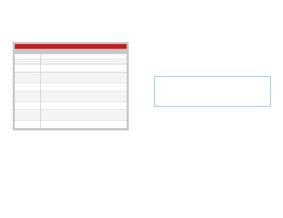
providing a visual indication to the user. Figure 22 gives the definitions of
the MODE_IND timings.
Reset to Factory Default
The transceiver is reset to factory default by taking the Pair line high briefly
4 times, then holding Pair high for more than 3 seconds. Each brief interval
must be high 0.1 to 2 seconds and low 0.1 to 2 seconds. (1 second
nominal high / low cycle). The sequence helps prevent accidental resets.
Once the sequence is recognized the MODE_IND line blinks the Reset
Acknowledgement defined in Figure 22 until the PAIR line goes low. After
the input goes low, the configuration is initialized. Factory reset also clears
the Paired Module table but does not change the local address.
If the PAIR input timing doesn’t match the reset sequence timing, the
module reverts to normal operation without a reset or pairing.
MODE_IND Timing
Module Status
Display
Transmit Mode
Solid ON when transmitting packets.
Receive Mode
Solid ON when receiving packets.
Pair Search
ON for 100ms, OFF for 900ms while searching for another unit
during the Pair process
Pair Found
ON for 400ms, OFF for 100ms when the transceiver has been
Paired with another transceiver. This is displayed for at least 3
seconds.
Pair Error
ON for 100ms, OFF for 100ms when the address table is full and
another unit cannot be added.
Remote Pair Error
ON for 100ms, OFF for 100ms, ON for 100ms OFF for 300ms
when the remote unit’s address table is full and a Pair cannot be
completed.
Pair Canceled
ON for 100ms, OFF for 200ms, ON for 100ms when the Pair
process is canceled.
Reset
Acknowledgement
ON for 600ms, OFF for 100ms, ON for 200ms, OFF for 100ms,
ON for 200ms and OFF for 100ms when the reset sequence is
recognized.
Extended Pair
Completed
Solid ON when the pairing operation is completed and waiting for
the PAIR line to go low.
Figure 22: MODE_IND Timing
Using the RSSI Line
The module’s Received Signal Strength Indicator (RSSI) line outputs a
voltage proportional to the incoming signal strength. The RSSI Voltage vs.
Input Power graph in the Typical Performance Graphs section shows the
relationship between the RSSI voltage and the incoming signal power. This
line has a high impedance so an external buffer may be required for some
applications.
The RSSI line updates once a second showing either the strength
of the packet received within the last second or the current channel
measurement. The formula to convert the RSSI voltage to power in dBm is:
P
RX
= (V
RSSI
/ V
CC
) * 60 – 105
The RSSI output can be utilized during testing or even as a product feature
to assess interference and channel quality by looking at the RSSI level with
all intended transmitters shut off.
Using the LATCH_EN Line
The LATCH_EN line sets the outputs to either momentary operation or
latched operation. During momentary operation the outputs go high for as
long as control messages are received instructing the module to take the
lines high. As soon as the control messages stop, the outputs go low.
During latched operation, when a signal is received to make a particular
status line high, it will remain high until a separate activation is received to
make it go low. The transmission must stop and the module must time out
before it will register a second transmission and toggle the outputs.
When the LATCH_EN line is high, all of the outputs are latched. A serial
command is available to configure latching of individual lines.
Note:
The RSSI levels and dynamic range vary from part to part. It is also
important to remember that the RSSI output indicates the strength of
any in-band RF energy and not necessarily just that from the intended
transmitter; therefore, it should be used only to qualify the presence and
level of a signal. Using RSSI to determine distance or data validity is not
recommended.