Linx Technologies TRM-xxx-TT User Manual
Page 8
Advertising
– –
– –
10
11
0
0.5
1
1.5
2
2.5
3
3.5
-21
-31
-41
-51
-61
-71
-81
-91
-101
-111
RSSI Output Voltage (V)
RF Input Power Level (dBm)
-40°C
25°C
85°C
0.1
0.15
0.2
0.25
0.3
0.35
2.5
3.3
5.5
Standby Icc (mA)
Supply Voltage (V)
-40°C
25°C
85°C
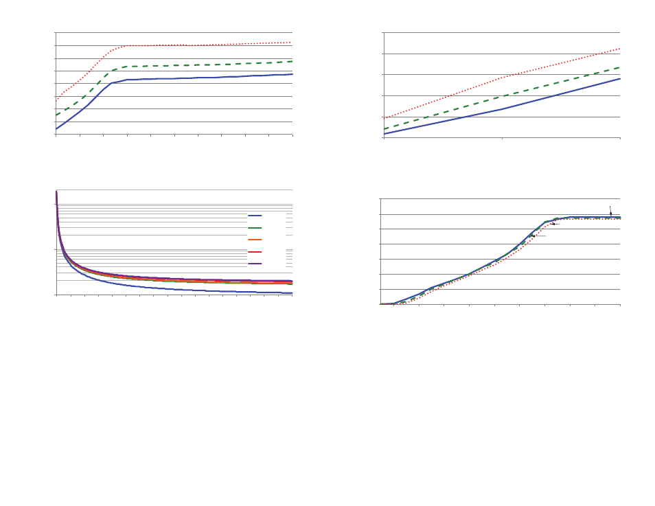
Figure 16: TT Series Transceiver Standby Current Consumption vs. Supply Voltage
Figure 17: TT Series Transceiver RSSI Voltage vs. Input Power
0.1
1
10
0
15 30 45 60 75 90 105 120 135 150 165 180 195 210 225 240 255
Average Current (mA)
Duty Cycle (s)
2.5VDC
3.0VDC
3.3VDC
5.0VDC
5.5VDC
13.5
14
14.5
15
15.5
16
16.5
17
17.5
2.5
2.8
3.1
3.4
3.7
4
4.3
4.6
4.9
5.2
5.5
RX Icc (mA)
Supply Voltage (V)
-40°C
20°C
85°C
Figure 14: TT Series Transceiver RX Current Consumption vs. Supply Voltage
Figure 15: TT Series Transceiver Average RX Current Consumption vs. Duty Cycle
Advertising