RISCO Group WatchOUT 315DT User Manual
Page 15
WatchOUT 315DT Installation Manual
15
English
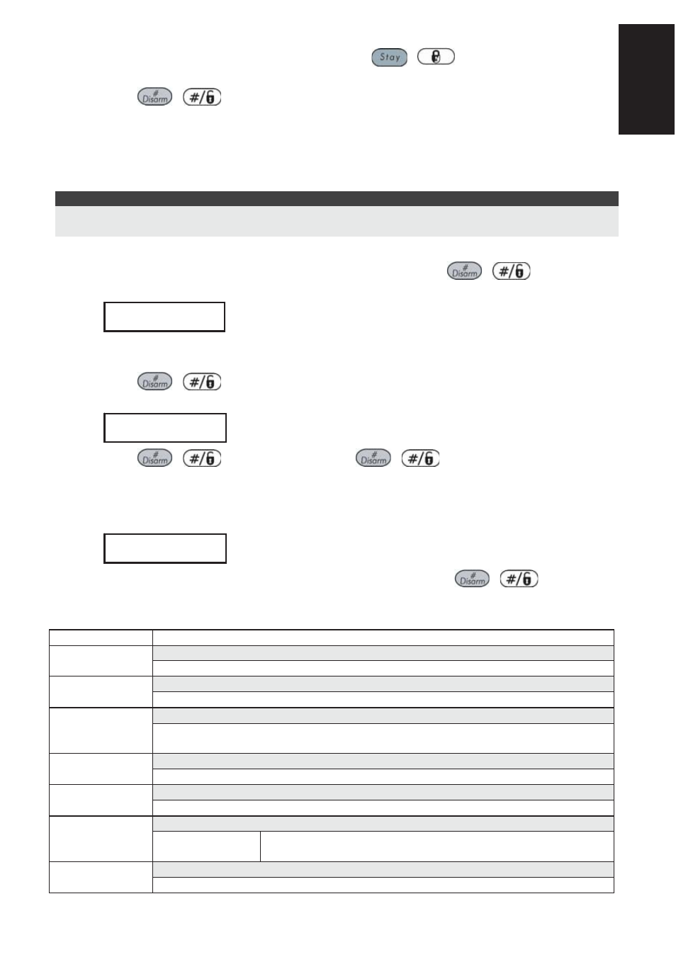
3. Place the cursor on the TYPE field and use the
/
key to select ODT15 for the
WatchOUT DT detector.
4. Press
/
to confirm.
5. Repeat the process for the other BUS detectors.
2. Assigning the WatchOUT DT to a Zone
1. From the main installer menu enter Zones: One by One option (Quick key [2][1])
2. Select the zone number that you want to assign the BUS detector.
Note:
If you defined a BUS Zone Expander, select a zone number from the virtual zones (defined by the BUS zone
expander).
3. Define Partitions, Groups, Zone Type and Zone Sound.
4. In the Termination category select [5] BUS Zone followed by
/
.
The following display appears:
Z:001 LINK TO:
ID:01 TYPE=ODT15
Z:001 LINK TO:
ID:01 TYPE=ODT15
5. Select the BUS zone number to assign to the programmed zone. The type field will be
updated automatically when selecting the zone.
6. Press
/
. The loop response category is not applicable to a BUS zone and the
following display appears:
Z:001 RESPONSE:
N/A-BUS ZONE
Z:001 RESPONSE:
N/A-BUS ZONE
7. Press
/
, assign label and press
/
.
3. Configuring the WatchOUT DT Parameters
1. To access the WatchOUT settings option press [2][0][3] from the main installer menu. The
following display appears:
B-ZONE PRMS:
ZONE#=001 (M:ZZ)
B-ZONE PRMS:
ZONE#=001 (M:ZZ)
2. Select the zone that the BUS zone was assigned to and press
/
. You can
now program the WatchOUT parameters as follows:
Zones Miscellaneous: BUS Zone
Quick Keys
Parameter
Default
[2][0][3][zzz]
[1]
LEDS
3 LEDS
Defines the LEDS operation mode.
[2][0][3][zzz]
[1][1]
Off
Disables the LEDS operation.
[2][0][3][zzz]
[1][2]
Red Only
Only the Red led will operate. This option is highly recommended to avoid the
possibility that the intruder will “Learn” the detector behavior.
[2][0][3][zzz]
[1][3]
3 LEDS
All 3 LEDs will operate.
[2][0][3][zzz]
[2]
PIR Sensitivity
Normal
Defines the sensitivity of the detector(MW + PIR)
[2][0][3][zzz]
[2][1]..[4]
Sensitivity Options
1) Low
2) Medium
3) Normal
4) High
[2][0][3][zzz]
[3]
MW Range
Trimmer
Defines the microwave channel range. The maximum is 23m.