English wall mount installation, Flat mounting, 45° angle mounting (left side mounting) – RISCO Group WatchOUT 315DT User Manual
Page 5
WatchOUT 315DT Installation Manual
5
English
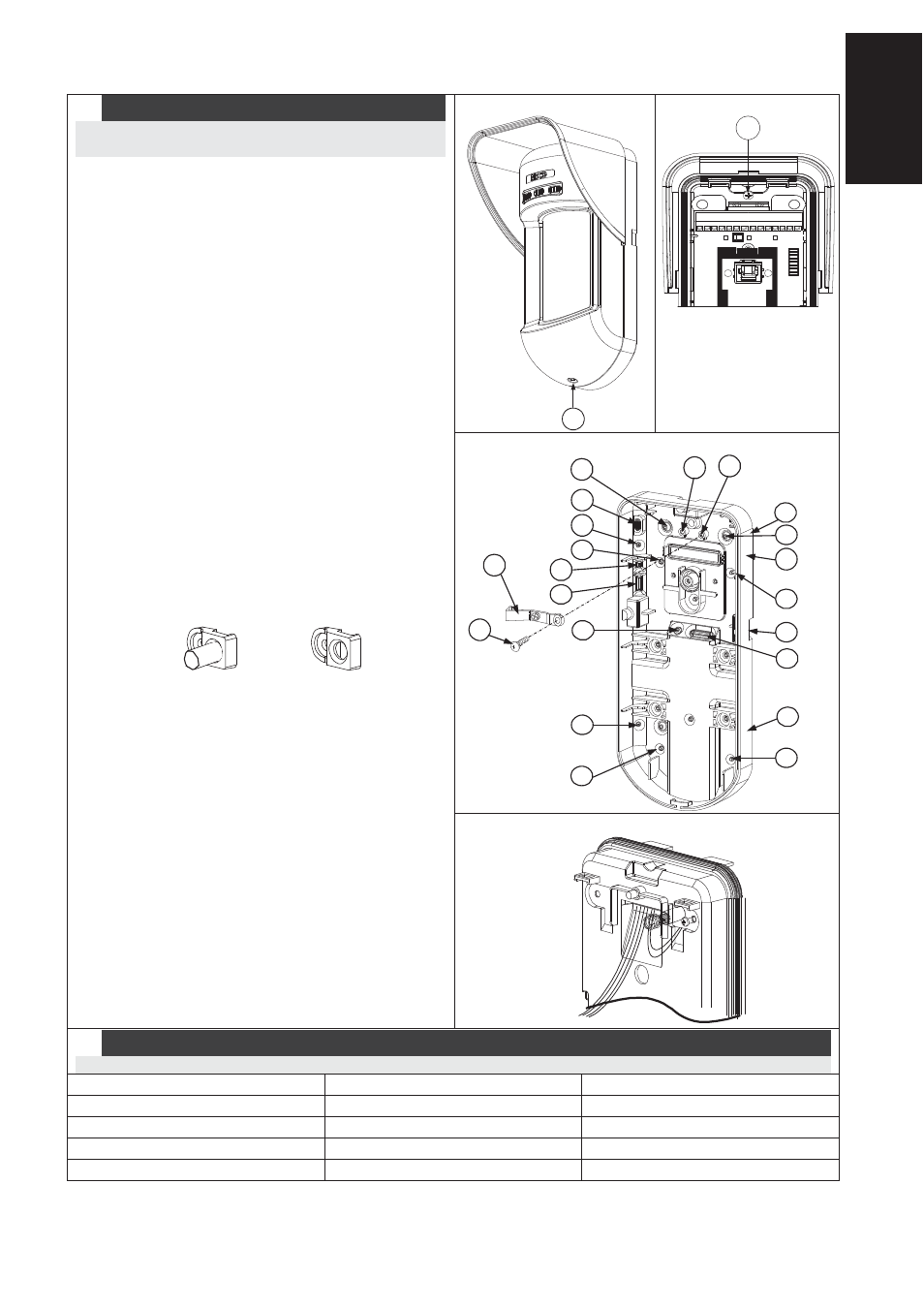
Wall Mount Installation
Note:
The installation knockouts numbering are marked on
the back plate.
1. Open WatchOUT front cover
(unlock C1, Figure 1).
2. Release internal base (unlock I1, Figure 2).
3. Select mounting installation as follows:
Flat Mounting:
Open knockouts on external base (Figure 3).
• B1 - B4: Wall mounting knockouts
• T1: Back tamper knockout
• W2 / W3: wires entry knockouts
45° angle Mounting (Left side
mounting)
a. Open knockouts on external base
(Figure 3)
• L1, L2: Left mounting knockouts
• T3: Left tamper knockout
• W5 / W6: Wire entry knockouts
b. Remove tamper spring.
c. Replace tamper bracket (Item 1) with
supplied flat tamper bracket (Item 2).
Item 1
Item 2
d. Insert Tamper lever B onto T5 and T3
and secure screw A (Figure 3).
4. Insert external wires through external base
W2, W3 (Flat Mounting) or W5, W6 (Left
side
mounting) (Figure 3).
5. Secure external base to the wall.
6. Insert external wires and tamper wires
through internal base (Figure4).
7. Secure internal base to external base (lock
I1, Figure2).
8. Close the front cover (Lock C1, Figure1)
after wiring and setting DIP switches.
9. Walk test the detector.
Figure 1
C1
Figure 2
l1
Figure 3
Tamper
Lever
A
T5
T1
B2
W9
B3
W2
B
L1
T3
B1
L2
W3
B4
R1
R2
(not visible)
T2
T6
(not visible)
T4
W5
W6
Figure 4
Note:
For 45° right side installation use the equivalent units on the external base as follows:
Knockouts Description
Left
Right
Mounting Knockouts
L1, L2
R1, R2
Tamper spring knockouts
T1,T3
T2,T4
Tamper screw anchor
T5
T6
Wiring Knockouts
W5, W6
W7, W8