Probe compensation, To connect the logic probe – RIGOL MSO/DS4000 Series User Manual
Page 49
RIGOL
MSO4000/DS4000 Quick Guide
7
Probe Compensation
When the probes are used for the first time, you should compensate the probes to
match the input channels of the oscilloscope. Non-compensated or poorly
compensated probes may cause measurement inaccuracy and error. The probe
compensation procedure is as follows:
1. Perform step 1, 2, 3 and 4 of “Function Inspection” in the previous section.
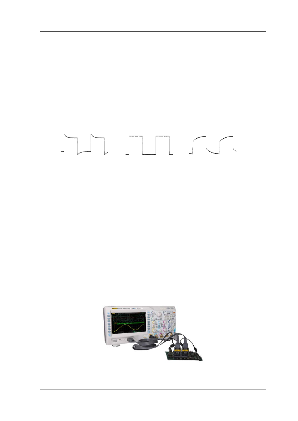
2. Check the displayed waveforms and compare them with the following figures.
Figure 9 Probe Compensation
3. Use a nonmetallic driver to adjust the variable capacitor on the probe until the
displayed waveform is as the “Perfectly compensated” in the figure above.
To Connect the Logic Probe
RIGOL provides logic probe for the MSO4000 series digital oscilloscope. For detailed
technical information of the logic probe, please refer to the corresponding Probe
User’s Guide.
Connect the logic probe single head to the digital channel input terminal [LOGIC
D0-D15] at the front panel of the MSO4000 series digital oscilloscope. Note:
connect the logic probe adaptor supplies with the accessories to the corresponding
branch header (called channel group) before connecting the logic probe to the device
under test.
Figure 10 To Connect the Logic Probe
Over compensated Perfectly compensated Under compensated