RIGOL MSO/DS4000 Series User Manual
Page 64
RIGOL
MSO4000/DS4000 Quick Guide
22
setting: channel coupling (e.g. in AC coupling), bandwidth limit (e.g.
when bandwidth limit is enabled) and input impedance (e.g.
when the input impedance is 50Ω).
17. Message Box
Display prompt messages.
18. Digital Channel Status Area
Display the current state of the 16 digital channels. It is D0 to D15 from right
to left. The digital channels currently enabled are displayed in green and the
digital channel currently selected is highlighted in red. Any digital channel
that is turned off will be grayed out in the Digital Channel Status Area.
Note: this function is only available for MSO4000 series digital oscilloscope.
19. Notification Area
Display system time, sound icon and USB storage device icon.
System Time: displayed in “hh:mm (hour:minute)” format. When
printing or storing the waveform, the output file will contain this time
message. Press Utility System
System Time to set the time in
the following format:
yyyy-mm-dd hh-mm-ss (year-month-date hour-minute-second)
Sound Icon: when sound is enabled, is displayed. Press Utility
Sound to turn the sound on or off.
USB Storage Device Icon: when the oscilloscope detects a USB storage
device,
is displayed.
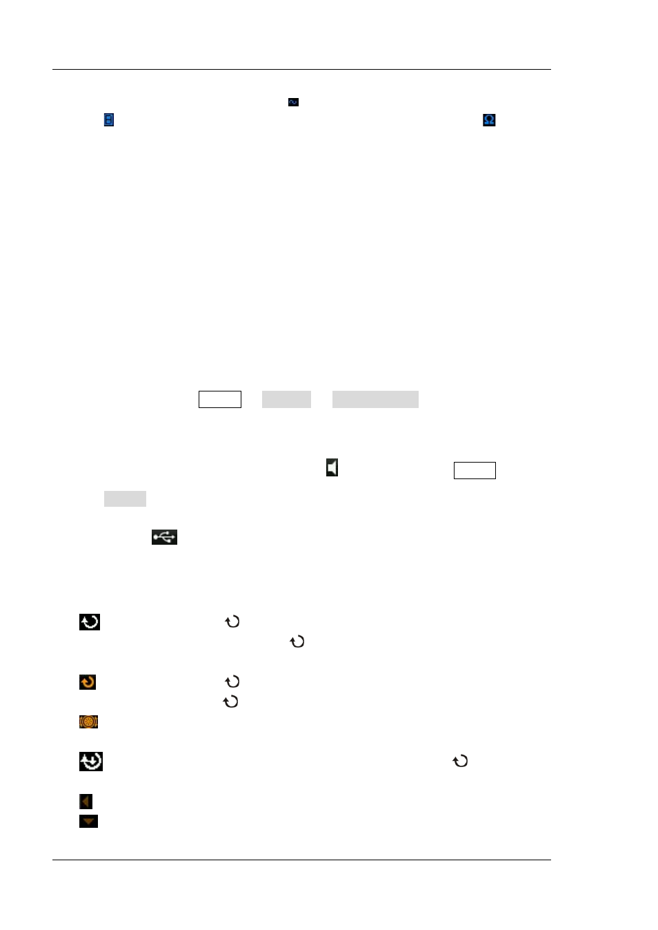
20. Operation Menu
Press any softkey to activate the corresponding menu. The following
symbols might be displayed in the menu:
Denote that
at the front panel can be used to select parameter
items. The backlight of
turns on when parameter selection is
valid.
Denote that
can be used to modify parameter value. The
backlight of
turns on when parameter input is valid.
Denote that you can use the nevigation knob to quickly adjust/locate
parameters.
Denote that users can rotate and then press down
to select the
desired parameter.
Denote that the current menu has several options.
Denote that the current menu has a lower level menu.