Specifications, Wiring, Mounting – Whelen 2519LPA User Manual
Page 2
Page 2
PERMANENT
MOUNT
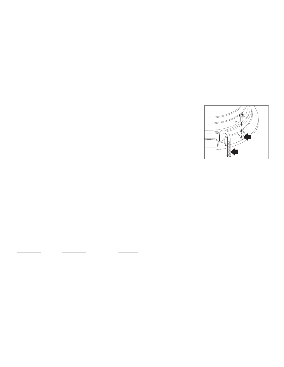
"J" HOOK
MOUNT
Fig. 1
The 2500 Series Beacon has fully encapsulated electronics that are
impervious to damage from moisture and vibration. The LED diagnostic
indicator displays the operational state of the electronic power supply and
flash tube. The unit features an automatic photocell Hi/Low feature which
can be overridden to maintain high intensity during nighttime operation.
This beacon also features Scan-Lock™ which allows you to choose
between 7 available flash patterns. There are 6 mounting options (Not all
included with beacon): mirror mount, permanent mount, pipe mount, J-
hook mount, magnetic mount, high base mount and Vacuum mount.
(Magnetic and Vacuum mount do not include Scan-Lock™ or Hi/Low.)
This beacon also features an easy to replace snap-in flash tube. All
models are SAE certified.
Specifications:
Model 2515 Series: SAE class 2 (all colors) 12-48 VDC
Input Power:...............................................................................21.5 watts
Output Power:............................................................. 15 watts / 13 joules
Input Current: ..............................................................1.7 amps / 12 VDC
......................................................................................0.9 amps / 24 VDC
......................................................................................0.5 amps / 36 VDC
......................................................................................0.3 amps / 48 VDC
Model 2519 Series: SAE class 2 (all colors) 12-24 VDC
Input Power:..................................................................................27 watts
Output Power:............................................................. 19 watts / 16 joules
Input Current: ..............................................................2.1 amps / 12 VDC
......................................................................................1.1 amps / 24 VDC
Model 2526 Series: SAE class 1 (all colors) 12-24 VDC
Input Power:..................................................................................37 watts
Output Power:............................................................. 26 watts / 22 joules
Input Current: ..............................................................2.9 amps / 12 VDC
......................................................................................1.5 amps / 24 VDC
IMPORTANT! All beacons in this manual should be fused at 5 AMPS.
IMPORTANT! Always be sure the drain hole (located on the bottom of
the base) is facing the rear of the vehicle after mounting.
WARNING: All customer supplied wires that connect to the positive
terminal of the battery must be sized to supply at least 125% of the
maximum operating current and FUSED at the battery to carry the
load. DO NOT USE CIRCUIT BREAKERS WITH THIS PRODUCT!
WARNING: The strobe light power supply is a high voltage device.
Do not touch or remove the strobe tube or assembly. Wait 10 minutes
after disconnecting the unit from power before starting any work or
trouble shooting on the power supply or system.
Wiring:
Listed below are the wire designations for the 2500 beacon. To extend the
beacons wires, use the wire gauge indicated below.
WIRE COLOR . . . . . . . . . . WIRE GAUGE . . . . . . . . . . . . . . . FUNCTION
RED. . . . . . . . . . . . . . . . . . 18 AWG . . . . . . . . . . . . . . . . . . . . . . . Positive
BLACK . . . . . . . . . . . . . . . 18 AWG . . . . . . . . . . . . . . . . . . . . . . . . Ground
VIOLET . . . . . . . . . . . . . . . 18 or 22 AWG . . . . . . . . High Power Override
WHITE-VIOLET. . . . . . . . . 18 or 22 AWG . . . . . . . . . . . . . . . . Scan-Lock
Mounting:
1 INCH (NPT) PIPE MOUNT:
Threading for a 1 inch (NPT) pipe mounting is precast in the base.
1.
Feed power cable through the 1 inch pipe and connect the cable to
the wires of the beacon.
2.
Screw the beacon into the threads on the 1” pipe, taking precaution
not to damage the connected power wires. Do not tighten base too
hard as not to damage threads on base.
PERMANENT MOUNT:
1.
Use the base as a template and mark the three mounting holes off
onto the mounting surface. Remove base. In the center between the
three mounting holes, mark the location of the wire access hole.
2.
Drill the mounting holes with a #16 drill bit. Drill the wire access hole
using a 3/8” drill bit. Remove any burrs from the wire access hole and
It is also recommended that you install a rubber grommet (customer
supplied) into the wire hole to protect the wires.
3.
The base seal (ITEM 21) will be used between the strobe beacon
base and the mounting surface.
4.
Feed the wires first through the base seal and then through the cable
access hole and place the base (with seal) on the mounting surface
(while lining up the mounting holes in the base with the mounting
holes you drilled into the mounting surface). Secure the beacon
firmly to the mounting surface with the supplied mounting screws.
“J” HOOK MOUNT:
This beacon is equipped to handle the “J” hook mount available on some
beacons. Be sure to use the
correct “J” hook mounting holes
(Fig. 1).
TEMPORARY MOUNT:
IMPORTANT WARNING: The
use of any magnetically
mounted warning device on
the outside of a vehicle in
motion is not recommended
and is at the sole risk and
responsibility of the user.
Magnetic/suction: Thoroughly
clean the proposed mounting surface prior to mounting. For suction cup
mounting, wipe the suction cup clean, place the beacon onto its mounting
surface and apply gentle pressure to ensure a good seal has been
achieved. The Magnetic/Suction Cups mount the same way as standard
suction cups but are best suited to a flat, steel surface. Magnetic: Place
the beacon onto the mounting surface and plug it into the vehicle cigar
lighter. The magnetic mount models do not offer Scan-Lock, Cruise Light,
Low Power or SYNC.
HIGH BASE MOUNT:
NOTE: The high base will also accept a 1 inch NPT pipe mount.
1.
Install the supplied rubber wire grommet into the high base and feed
the beacon wires through the grommet.
2.
Install the three fastex grommets into the high base as shown then,
using the 3 sheet metal screws from the existing base, secure the
existing base to the high base.
3.
Using the base as a template mark off the two mounting hole
locations onto the mounting surface. Remove the base and in the
center mark the location of the wire access hole.
4.
Drill mounting holes into the mounting surface with a drill sized for
#10-24 mounting screws (customer supplied). Drill the wire access
hole using a 3/8” drill bit. Remove any burrs from the wire access
hole and it is also recommended that you install a rubber grommet
(customer supplied) to protect the wires.
5.
The base seal will be used between the strobe beacon base and the
mounting surface.
6.
Feed the wires first through the base seal and then through the wire
access hole and place the base (with seal) on the mounting surface
(while lining up the mounting holes in the base with the mounting
holes you drilled into the mounting surface). Secure the beacon
firmly to the mounting surface with your mounting screws.
NOTE: Power readings on all models were
taken with the beacon operating in CometFlash®.