Operation: programming / scan-lock™ / white-violet, High power override: violet, Led diagnostic indicator – Whelen 2519LPA User Manual
Page 3: Replacing the flashtube, Fig. 2
Page 3
Base Seal
Rubber
Grommet
Rubber
Grommet
F a s t e x
Grommet
R u b b e r
Grommet
Customer
supplied
hardware
Dimples in bottom of
base. Punch out to
accomodate mounting
screws.
Botto
m view of b
ase
HIGH BASE / PERMANENT
MOUNT
This is a tamper-proof way to
secure the beacon. Mounting
screws are hidden inside the
base, and aren’t accessible
unless unit is dismantled.
1.
Locate the 3 dimples on the
bottom of the base. Drill
them out with a .218 dia.
drill bit for #10 sheet metal
screws (customer
supplied).
2.
Using the base as a
template mark the 3
mounting holes off onto the
mounting surface. Remove
the base and in the center
mark the location of the
wire access hole.
3.
Drill the mounting holes into
the mounting surface to fit
your mounting hardware
then drill the wire access
hole using a 3/8 inch drill
bit. Remove burrs from the
wire access hole to prevent
damage to the wires. It is
recommended that you
install a rubber grommet in
the wire access hole (customer
supplied).
4.
The gasket will be used
between the base and the
mounting surface.
5.
Feed the wires through the
cable access hole and
place the base with the
gasket on the mounting
surface, lining up the
mounting holes in the base
with the ones in the mounting
surface. Secure base firmly to
mounting surface with your hardware
and reassemble beacon.
Operation:
Programming / Scan-Lock™ / White-Violet:
To cycle through all patterns: With the beacon switched on, apply
Positive (+) voltage to the WHITE-VIOLET wire for less than 1 second and
release to cycle forward. Apply Positive (+) voltage for more than 1 second
and release to cycle backward.
To set a pattern as default: When the desired pattern is displayed, allow
it to run for more than 5 seconds. The beacon will now display this pattern
when activated.
To reset to the factory default pattern: Turn off power. Now, while
applying Positive (+) voltage to the WHITE-VIOLET wire, turn power on.
Available Scan-Lock™ Patterns:
Comet Flash® (Default Pattern) . . . . . . . . . . . . . . . . . . . . . . . . . .70 FPM
TripleFlash™ . . . . . . . . . . . . . . . . . . . . . . . . . . . . . . . . . . . . . . . . .80 FPM
DoubleFlash. . . . . . . . . . . . . . . . . . . . . . . . . . . . . . . . . . . . . . . . . .90 FPM
SingleFlash . . . . . . . . . . . . . . . . . . . . . . . . . . . . . . . . . . . . . . . . .120 FPM
ModuFlash™ . . . . . . . . . . . . . . . . . . . . . . . . . . . . . . . . . . 60-120-60 FPM
ActionFlash™. . . . . . . . . . . . . . . . . . . . . . . . . . . . . . . . . . . .Comet-Single
ScanFlash™ . . . . . . . . Comet-Single-Triple-Single-Double-Single-Repeat
High Power Override: Violet
This beacon is equipped with photocell Hi/Low. This means the beacon
will automatically step down to low power at night. If you wish to keep the
beacon in high power at night, ground the VIOLET wire. This will cause
the beacon to stay in high power until you remove the ground. In
applications requiring SAE compliance, this line should be permanently
grounded.
LED Diagnostic Indicator:
This strobe beacon comes equipped with an LED diagnostic indicator. If
the flash tube does not light and the LED is blinking, replace the flash
tube. If the flash tube does not light and the LED is not blinking, check the
power wires, fuse or strobe power supply. The LED is located under the
lens (Fig. 2).
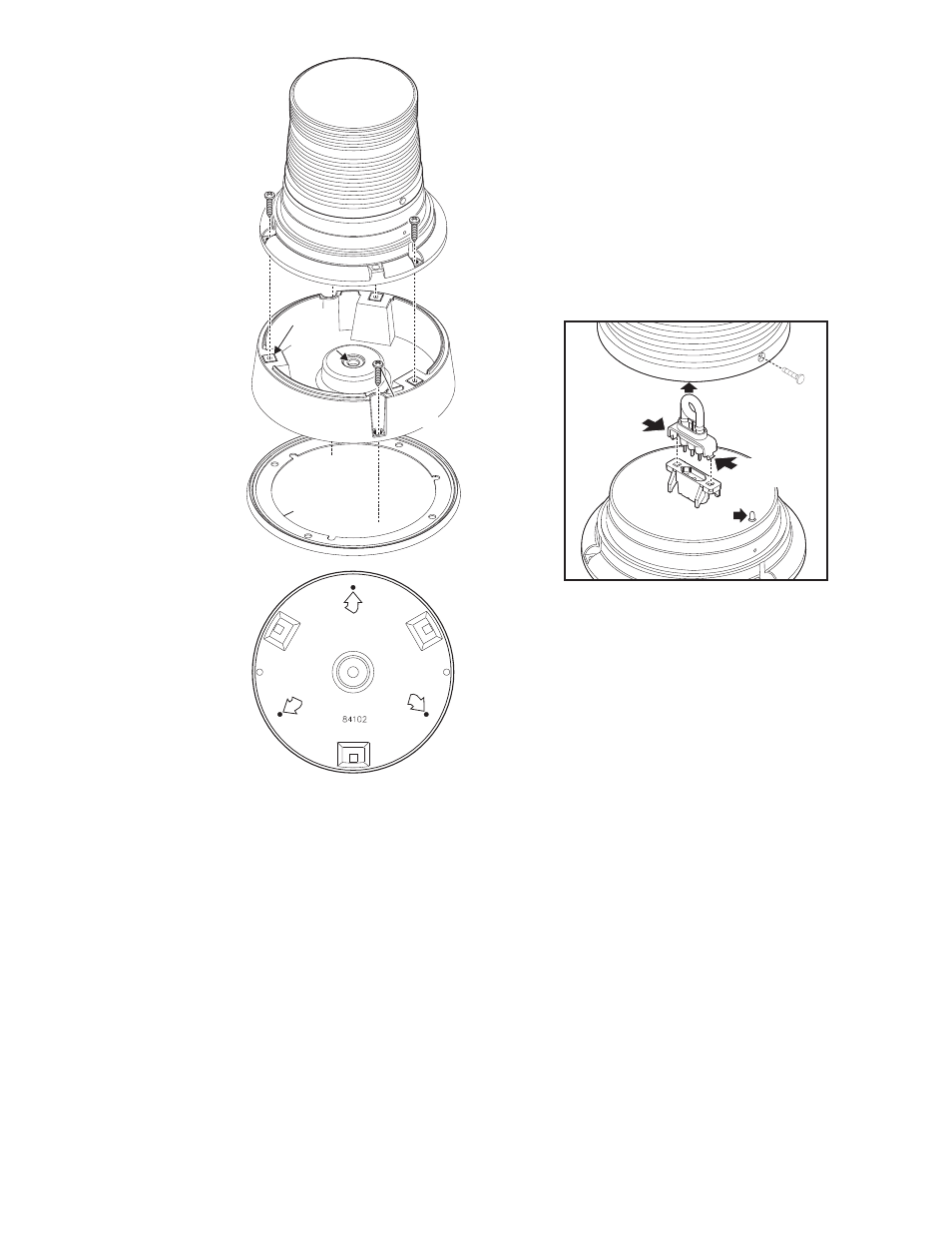
Replacing the Flashtube:
1.
Remove the lens screws and remove the lens.
2.
While pinching the 2 clips on the sides of the flastube together, pull
the old flash tube out of the beacon.
3.
Plug the new flash tube into the base and replace the lens.
IMPORTANT! It is the responsibility of the installation technician to
make sure that the installation and operation of this product will not
interfere with or compromise the operation or efficiency of any
vehicle equipment! Before returning the vehicle to active service,
visually confirm the proper operation of this product, as well as all
vehicle components/equipment.
LED
INDICATOR
1. Remove
lens screws
4. Lift out old tube.
Fig. 2
Fig. 2
REMOVE
LENS
REMOVE
LENS
2. Remove
lens
Fig. 2
3. pinch pins together
to release tube from
base while lifting.