Whelen 800DHAP User Manual
Page 2
Page 2
The 800D Series Strobe Beacon features a combination base which may
be used for either Flange Mount, 1” (NPT) Pipe Mount, Permanent Mount,
Magnetic or Magnetic-Suction mount. The threading for a 1 inch (NPT)
pipe mounting is precast in the die-cast base.
WARNING! The strobe light power supply is a high voltage device.
Do not remove strobe tubes or dismantle strobe light head
assemblies in the system while it is in operation. Wait 10 minutes
after turning off power before starting work or any trouble shooting.
•
Input Voltage: 12VDC and 24VDC
•
Input Current: 2.5A @12.8V and 1.5A @ 25.6V
•
Output Power: 25 Watts
•
4 Selectable Flash Patterns.
•
Selectable Manual Hi/Low Intensity Mode.
•
Automatic Photocell Hi/Low Intensity Mode (Optional).
•
Flange / Pipe / Permanent / Magnetic-Suction Mounting.
•
Hi/Off/Low Intensity Switch. (Optional)
•
4 Pattern Beacon Controller with Diagnostic & Manual Hi/
Low Intensity Control. (Optional)
•
Factory Installed Cruise Light. (Optional)
Installation: FLANGE MOUNT
1.
Using the base gasket as a template, mark the three mounting holes
and the center wire access hole onto the mounting surface.
2.
Drill holes for the three 10 X 5/8” pan head sheet metal mounting
screws. (supplied)
3.
Drill the wire access
hole using a 1/2” drill.
Install a rubber
grommet in the wire
access hole to
protect the wires.
4.
Place base gasket on
mounting surface
aligned with the holes
in the mounting
surface. After
connecting the strobe
beacon to the power
cable, feed the wires
through the wire
access hole. Place strobe beacon into proper position and slip
mounting collar over the strobe beacon to fit around base of the unit.
Align the three holes in the mounting collar with the three mounting
holes in the base gasket and mounting surface. Use the three
enclosed mounting screws to attach the strobe beacon to the
mounting surface.
Installation: PIPE MOUNT
1.
Feed power cable through the 1 inch pipe and connect the cable to
the wires of the 800D Series strobe beacon.
2.
Screw the beacon to the threads on the 1 inch pipe, taking precaution
not to damage the connected power wires.
Installation: PERMANENT MOUNT
This mounting of the 800D Series strobe beacon is a tamper proof way to
secure the unit to the mounting surface. The mounting screws are hidden
inside the base, and are not accessible unless the strobe beacon is
disassembled.
1.
Remove the polycarbonate optic dome from the base (see
“Removing Dome & Strobe Power Supply Assembly”).
2.
Locate the four dimples
equally spaced within the
perimeter of the die-cast base
of the power supply
assembly. Punch these
dimples out to create a hole
for the mounting screws.
3.
Using the base of the power
supply assembly as a
template mark the four
mounting holes on the
mounting surface. Mark in the
center between the four
mounting holes the location of
the wire access hole.
4.
Drill mounting holes in the mounting surface to fit customer supplied
mounting hardware. Also drill a wire access hole using a 1/2 inch
drill. Install a rubber grommet in the wire access hole to protect the
wires.
5.
Base gasket will be used between the strobe beacon base and the
mounting surface. Cut the gasket along perforation to fit the diameter
of the base.
6.
After connecting the strobe light beacon to the power cable, feed the
wires through the cable access hole and place the base with the
gasket on the mounting surface, lining up the mounting holes in the
base with the ones in the mounting surface. Secure the strobe light
beacon base firmly to the mounting surface with customer supplied
hardware.
7.
Reassemble the strobe light beacon.
Temporary Mounting (Magnetic, Suction Cup, etc.)
With the magnetic or magnetic/suction cup mounting options you will be
able to mount your strobe so that you can remove it if necessary and
avoid drilling.
Installation: Magnetic/suction
Thoroughly clean the proposed mounting surface prior to mounting. For
suction cup mounting, wipe the suction cup clean, place the beacon onto
its mounting surface and apply gentle pressure to ensure a good seal has
been achieved. The Magnetic/Suction Cups mount the same way as
standard suction cups but are best suited to a flat, steel surface.
Installation: Magnetic
Place beacon onto mounting surface and plug into vehicle cigar lighter.
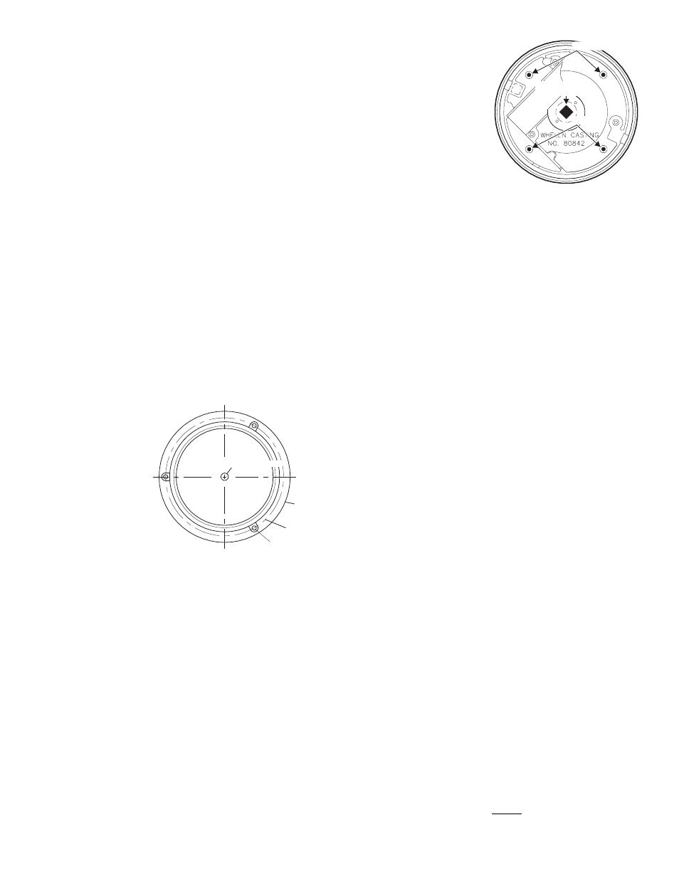
Removing Dome & Strobe Power Supply Assembly:
1.
Remove the polycarbonate optic dome from the base by removing
the two base screws (Fig. 11).
2.
Remove the 3 screws that hold down the strobe power supply
assembly and separate it from the base.
3.
Remove the spring clip and insulator.
See important information about removing spring clip on next page)
IMPORTANT: Be sure to tape or remove any unused wires.
WARNING! The use of any magnetically mounted warning beacon on
the outside of a vehicle while in motion is not recommended and is
at the sole discretion and risk of the use
WARNING! Beacons equipped with cigar cords are intended for
short duration, intermittent operation only! Prolonged operation
requires the beacon to be wired to the vehicle.
WARNING! All customer supplied wires that connect to the positive
terminal of the battery must be sized to supply at least 125% of the
maximum operating current and FUSED at the battery to carry that
load. DO NOT USE CIRCUIT BREAKERS WITH THIS PRODUCT!
PERMANENT
MOUNT
Dimples
Dimples
Drill wire access
hole here
1/2" Diameter
6.81"
Diameter
Base
5.937 B.C.
T h r e e
. 2 1 8
Diameter Holes
Equally spaced
#10 Clearance
FLANGE
MOUNT