Fig. 12, Battery, Flash pattern options – Whelen 800DHAP User Manual
Page 4: Customer options hi/low intensity option, Jumper options, Page 4
Page 4
BROWN
WHITE
BROWN
WHITE
BROWN
WHITE
BROWN
WHITE
CometFlash®
SingleFlash
DoubleFlash
ActionFlash™
BATTERY
MODEL 800D STANDARD. HIGH-OFF-LOW SWITCHING.
NOTE: Cut VIOLET
(looped) wire, run it out of
unit with BLK & RED wires.
When VIO wire is grounded,
you are in high mode When
VIO wire is floating you are
in low mode.
Switches & fuses are customer supplied. 5 AMP fuse:
3 AMP fuse:
.
12 VDC
24 VDC
Switch control wiring schematics / 800D Strobe Light Series
TO STROBE
LIGHT HEAD
DOUBLE POLE, DOUBLE THROW
CENTER OFF SWITCH (REAR VIEW)
TO STROBE
LIGHT HEAD
MODEL 800D STANDARD. ON/OFF SWITCHING / HIGH POWER ONLY.
BLK / NEG. (-)
RED POS (+)
/
.
ON/OFF
SWITCH
BLK NEG (-)
/
.
RED POS (+)
/
.
RED POS (+)
/
.
BLK NEG (-)
/
.
VIO NEG (-) HI/LOW
/
.
DOUBLE POLE, DOUBLE THROW
CTR. OFF SWITCH (REAR VIEW)
TO STROBE
LIGHT HEAD
MODEL 800D with CRUISE LIGHT OPTION.
NOTE: Cruise lt.
is 12 VDC or 24
VDC bulb.
NOTE: Strobe light is
controlled by DPDT
CENTER OFF switch
control, & cruise light is
controlled by ON/OFF
switch control.
BLK / NEG. (-)
RED POS. (+)
/
RED POS (+)
/
.
BLK NEG (-)
/
.
VIO NEG (-) HI/LOW
/
.
GRY POS (+) CRUISE LT, 12 OR 24 VDC
/
.
DOUBLE POLE, DOUBLE THROW
CENTER OFF SWITCH (REAR VIEW)
TO STROBE
LIGHT HEAD
NOTE: Cruise
Lt. is 12 VDC or
24 VDC bulb.
MODEL 800D WITH CRUISE LIGHT OPTION.
NOTE: Strobe
& cruise lights
are connected
to same DPDT
CENTER OFF
switch control.
BLK NEG (-)
/
.
RED POS (+)
/
.
RED POS (+)
/
.
BLK NEG (-)
/
.
VIO NEG (-) HI/LOW
/
.
GRAY POS (+) CRUISE L
12 OR 24 VDC
/
.
T.
FUSE
FUSE
FUSE
FUSE
1 AMP
F U S E
BATTERY
BATTERY
BATTERY
BATTERY
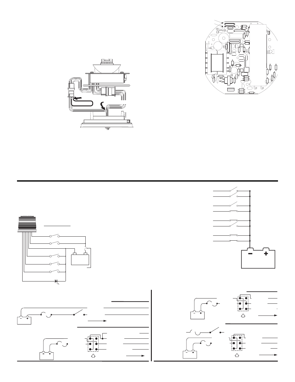
Flash Pattern Options:
The default flash pattern for the 800D is CometFlash®. You may choose
from several other patterns by making a few simple changes.
1.
Disassemble the unit as described under “Removing the Dome and
Strobe Power Supply
Assembly”.
2.
Locate the input control
pigtail assembly and
plug it in to the extra
connector coming out of
the Power Supply.
3.
Run the BROWN &
WHITE wires out
through the center of
the base as shown.
Tape off the unused
GREEN wire.
4.
Reassemble the unit and
you are ready to choose
your options.
To Select SingleFlash: Ground
the WHITE wire and tape off the
BROWN wire.
To Select DoubleFlash: Ground
the BROWN wire and tape off
the WHITE wire.
To Select ActionFlash™:
Ground both the WHITE and
BROWN wires.
IMPORTANT! Before returning
the vehicle to active service,
visually confirm the proper
operation of this product, as
well as all vehicle
components/equipment.
CUSTOMER OPTIONS
Hi/Low Intensity Option:
1.
Take dome and strobe power supply assembly apart. (see
“Removing Dome and Strobe Power Supply Assembly”)
2.
Locate the VIOLET (looped) wire, cut it at pin 2, and run it out of the
bottom of the unit with
the BLACK and RED
wires.
3.
Reassemble the unit.
4.
Now, if you ground
the VIOLET wire, your
light will run at high
intensity, and if you
tape off the VIOLET
wire, your light will run
at low intensity. You
may want to install a
two position switch so
that you can alter-
nate between the two
functions.
Jumper Options:
There are several options you can utilize by cutting one, both or neither of
the jumpers located inside the unit (the jumpers are labeled JU1 and
JU2.).
A.
You may operate your strobe at either high or low intensity (default
setting). Leave both jumpers intact and follow the instructions under
“Hi/Low Intensity Option”.
1 2 3
Cut VIOLET wire here
1234
4321
1 2 3
Extend through base here
Fig. 12
B.
Your strobe may also be
equipped with the
optional “Photocell
function”. This will auto-
matically adjust the
intensity of the strobe
light according to the
ambient light (darkness
switches the beacon to
low power, while day-
light switches the bea-
con to high power). To
engage this function
you must cut the JU2
jumper and leave the
JU1 jumper intact. Then
clip the VIOLET wire
and tape it off (see “Hi/Low Intensity Option”). Now the photocell
option is always engaged. If you want to be able to turn this function
on or off manually, you must also attach the VIOLET wire to a switch
that will ground or disconnect it. When you switch to “ground” the light
will always be at high intensity. When you switch to “disconnect” the
light will return to the photocell function.
C.
If you want your strobe to turn on automatically during the day and off
at night, cut the JU1 jumper and leave JU2 jumper intact.
D.
If you want your strobe to turn off automatically during the day and on
at night, cut both the JU1 and JU2 jumpers.
IMPORTANT NOTE: Both “C” and “D” are usually used for remote
applications. Once you convert to either of these functions you will not be
able use the light any other way.
®
Fuse:
12VDC - 5 AMP
24VDC - 3 AMP
(Customer Supplied)
GRY
CRUISE
WIRING DIAGRAM
ON/OFF
RED
BLK(GND)
HI/LOW CTRL
PATTERN 1
PATTERN 2
VIO
BRN
WHT
GRN
LED DIAG.
(+)
Battery
(-)