Whelen MBCV98AA User Manual
Page 2
Page 2
To Remove the Side Mirror Assembly:
1.
Remove the driver side door panel from the vehicle.
2.
Remove the three hex nuts that secure the mirror assembly to the vehicle. Unplug the mirror assembly harness cable from the door’s power
harness and carefully remove the mirror assembly from the vehicle.
The glamour cap will now be removed from the mirror assembly.
To Remove the Glamour Cap from the Mirror Assembly:
1.
To remove the glamour cap from the mirror assembly, the glamour caps three retaining tabs must be carefully
lifted off the rear housing retaining pins. This is accomplished with a small flatblade screwdriver or other
suitable device.
2.
To gain access to the glamour caps upper retaining tabs, the mirror must be gently positioned so that it’s lower
edge is pressed inwards as far as it will travel. This will allow the two, upper retaining tabs to be accessed with
the screwdriver.
3.
Position the screwdriver blade under either of the upper retaining tabs and pry tab upwards and off its retaining
pin. Repeat for remaining upper retaining tab.
4.
To gain access to the glamour cap’s lower retaining tab, the mirror must be gently positioned so that it’s upper
edge is pressed inwards as far as it will travel. This will allow the lower retaining tab to be accessed with the
screwdriver.
5.
Position the screwdriver blade over the retaining tab and pry tab downwards and off its retaining pin. With all three retaining tabs free, pull
glamour cap and its guide pin away from the mirror assembly.
The mirror assembly will now be prepared for the new strobe harness cable.
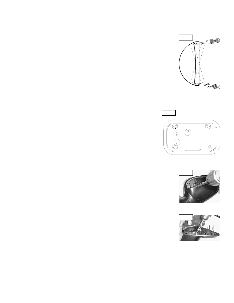
To Prepare the Mirror Assembly:
1.
With the glamour cover removed, look at the rear of the mirror assembly. Locate the upper
retaining tab slot indicated. Draw a perpendicular line that extends 1 inch from the middle of the
bottom of the slot.
2.
At the end of this perpendicular line, carefully drill a 1” hole into the mirror assembly.
3.
Now fold the lower section of the triangular foam mounting gasket so that access to the lower
section of the mirror assembly’s mounting surface is gained.
4.
Locate the area along the bottom of the mirror assembly’s mounting surface where the mirror
harness has been routed from inside the assembly. The adjacent passage (closer to the rear of the
assembly) will also be drilled using a 3/8” drill bit. As shown in Fig. 4, make sure that as the hole is
drilled, the bit stays parallel with walls of the passage.
NOTE: The location of these holes are critical. Be sure that the indicated distances are measured accurately. Failure to do so could result
in damage to the mirror’s motor and/or wiring components.
To Prepare the Strobe Harness:
NOTE: Because the strobe harness must be routed through a specific, narrow and twisting path within the
mirror assembly, it is necessary to temporarily extend the length of the harness with a make-shift “snake”.
1.
Locate the tie-wrap included with your Mirror-Beam™ and cut the fastener-end off.
2.
Locate the end of the strobe harness that has SOCKET-type terminals installed on the free wires. If present, cut
off the non-insulated wire (it is not used in this application).
3.
Strongly secure the tie-wrap to the strobe harness with electrical or similar tape. It is important to have a
sufficient length of the tie-wrap secured to the harness jacket (at least 2”).
The strobe harness will now be routed through the mirror assembly.
Routing the Strobe Harness:
1.
Insert the end of the tie-wrap through the 3/8” hole drilled in step 4 of the “To prepare the mirror assembly...”
section.
2.
Feed the tie-wrap through the mirror assembly until the tie-wrap can be pulled through the 1” hole drilled in step
2 of the “To prepare the mirror assembly...” section. There should not be more than 4 or 5 inches of harness
sticking out of the hole. If the length is different from this, adjust harness length accordingly.
The tie-wrap is now removed from the harness and the wire terminals inserted into their 3 position connector
(supplied) as follows (For detailed information, refer to the instruction tag attached to the harness):
Position 1 = Red Position 2 = Black Position 3 = White (Clear)
Fig. 3
Fig. 4
Side View
1“
Inch
Left (Driver) Side Mirror
(Rear view with Glamour Cap removed)
Fig. 1
Fig. 2