Page 3, Re-assembling the mirror-beam™ assembly – Whelen MBCV98AA User Manual
Page 3
Page 3
10
2
2
2 1 - 1 2 0 8 0 9 0 5 - 1
9
11 - 4 8 4 2 2 9 - R 0 0
8
7
6
5
4
3
2
1
1
1
1
1
1
11 - 4 8 4 2 2 9 - L 0 0
6 8 - 3 9 6 3 2 2 8 - 1 0
6 8 - 3 9 6 3 2 2 8 - 2 0
6 8 - 3 9 6 3 2 2 8 - 3 0
6 8 - 3 9 6 3 2 2 8 - 4 0
6 8 - 3 9 6 3 2 2 8 - 5 0
11 - 7 6 3 2 2 6 - 0 0 0
1 5 - 0 8 1 2 1 B - 0 8 2
HOUSING DRIVER SIDE - CROWN VICTORIA
/
LENS / REPLACEMENT / NON-OPTIC / AMBER
LENS / REPLACEMENT / NON-OPTIC / BLUE
LENS / REPLACEMENT / NON-OPTIC / CLEAR
LENS / REPLACEMENT / NON-OPTIC / GREEN
LENS / REPLACEMENT / NON-OPTIC / RED
BLACK FLANGE
SCREW, #8 X 1/2" PPHSMS SS BLACK ZINC OXIDE
ITEM
QTY QTY
PART NUMBER
0 1 - 0 6 8 3 6 0 8 0 _ S
_
0 1 - 0 6 8 3 6 0 9 0 _ S
_
DESCRIPTION
MIRROR BEAM / DRIVER SIDE / STROBE - CROWN VICTORIA
MIRROR BEAM / PASSENGER SIDE / STROBE - CROWN VICTORIA
HOUSING PASSENGER SIDE CROWN VICTORIA
/
/
15
14
13
12
11a
1
1
1
2
1
1
1
2
2 6 - 0 3 1 5 0 0 1 - 1 4
0 1 - 0 4 1 5 5 3 2 - 0 0
4 6 - 0 7 4 2 1 7 2 - 1 5
6 6 - 0 4 1 6 6 4 2 - 0 0
1 5 - 0 8 1 4 1 A - 0 8 0
14 1/2" BLACK TY-WRAP (NOT SHOWN)
CABLE INSTALLATION KIT
3/C CABLE ASSEMBLY
MOUNTING TAPE (NOT SHOWN)
#8 SCREW GROMMET
11
1 5 - 0 8 1 4 1 A - 0 8 0
2
2
2
2
NOTE: If your housing contains pressed-in metal threaded inserts, use item
to secure
the lighthead. If it does not, use items
and
to secure the lighthead.
11a
10
11
SCREW / 10-24 X3/4"P.P.H.M.S.
SCREW / #8 X 5/8" P.P.H.S.M.S.-S.S.
1
16
1
1
0 2 - 0 3 6 3 2 9 2 - 0 0
LINEAR STROBE REFLECTOR ASSEMBLY
13
14
7
6
5
4
3
2
1
9
8
10
11 11a
16
Affixing the Mirror-Beam™ Housing to the Mirror Assembly:
NOTE: The following procedure requires that the mirror assembly be no colder than 60°F (18°C).
1.
Thoroughly clean the plastic mirror assembly and the inside surface of the housing using a 50/50 mixture of
isopropyl (not rubbing) alcohol and water. Dry completely.
2.
Locate the 6” strips of double-sided adhesive tape included with your MirrorBeam.
3.
Position one 6” strip on top of the mirror assembly. When properly positioned, the tape will be centered
between the inboard and outboard ends of the mirror assembly and the leading edge of the tape will be set
back approximately 1/4” from the rear (mirror side) edge of the assembly. After the tape is positioned, it is
important to press firmly on the protective backing so that the tape adheres to the surface.
4.
Cut the remaining 6” length of tape in half. A 3” length must be adhered in a specific location. On the bottom
of the mirror assembly, locate the mold seam. Position the tape in the location 1/4” back away from this
seam.
5.
Fold the protective backing strips on the top and bottom tape strips so that 1/2” to 3/4” of backing is
extended over the edge of the mirror assembly (or the mold seam, in the case of the bottom tape). Trim and remove the exposed tape.
6.
Place the mirror assembly mirror-side down on the workbench. Mount the MirrorBeam housing onto the mirror assembly. The housing must fully
engage the mirror assembly!
7.
The protective backing strips must now be removed. To accomplish this, the housing must not be in contact with the backing strips. Using a small, flat
blade screwdriver (or similar tool) gently pry the housing about 1/4” away from the mirror assembly. Carefully pull the protective strip “tab” created in
step 5, and gently remove it completely from the tape strip. Do not allow the MirrorBeam housing to shift while removing the backings. Also, do not
allow the strip to tear while being removed.Repeat process for the remaining tape strip.
8.
Apply pressure to the MirrorBeam assembly at the tape locations. Maintain pressure for a minimum of 20 minutes to allow the tape to properly setup.
This can be accomplished by wrapping the MirrorBeam/mirror assembly tightly with adhesive tape. (See important adhesion information below.)
9.
Using a 1/8” drill bit and the MirrorBeam housing as a template, drill a hole into the mirror
housing. Locate the #8 x 1/2” sheet metal screw (included) and secure the MirrorBeam
housing to the mirror housing.
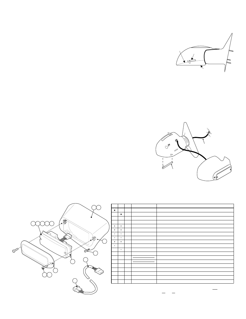
Re-assembling the Mirror-Beam™ Assembly:
1.
Re-connect the mirror assembly to it’s main power harness. Route the MirrorBeam harness
through the door, along the same path as the vehicle’s main power harness and finally to the
strobe power supply mounted in the vehicle.
2.
Cut the non-insulated wire off the strobe harness. Insert the PIN-type terminals into the
provided connector as detailed in the “Routing the strobe harness...” section of this manual.
Insert plug into power supply and confirm proper strobe operation.
3.
Using the original hardware, remount the mirror onto the vehicle.
IMPORTANT! The tape adhesive used in this procedure is fully bonded after 72 hours @ 70°F
(21°C). During this period, do not expose the Mirror-Beam™ to any un-necessary force, such
as the high-pressure water from a car wash.
NOTE: The outer surfaces of this product may be cleaned with mild soap and water. Use of any other chemicals may void product warranty.
Do not use a pressure washer.
3M #4396
6" Tape
15’ Strobe
Cable
Mold
Seam
Tape
Location
Mirror