Mounting, Flange mounting, Permanent mounting – Whelen PT360P User Manual
Page 2: Fig. 1, Fig. 2, Fig. 3
Page 2
Mounting:
Caution:
Permanent mounting of this product will require drilling.
It is absolutely necessary to make sure that no other vehicle
components could be damaged by this process. Check both sides of
the mounting surface before starting. If damage is likely, select a
different mounting location. It is the responsibility of the installation
technician to make sure that the installation and operation of this
product will not interfere with or compromise the operation or
efficiency of any vehicle equipment! Before returning the vehicle to
active service, visually confirm the proper operation of this product,
as well as all vehicle components/equipment.
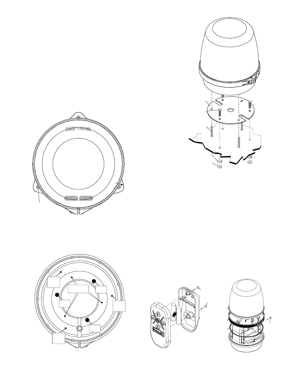
Flange Mounting:
1. Secure the flange mount plate to the beacon base using the supplied
8 X 1/2” Phillips Flat Head Sheet Metal Screws (Fig. 1).
2. Place the beacon onto the mounting surface and mark off the 3
mounting hole locations onto the mounting surface.
3. Drill the 3 mounting holes (sized for the supplied screws) and secure
the beacon to the mounting surface using the supplied 10 X 1” Phillips
Pan Head Sheet Metal Screws.
Permanent Mounting:
1. Place the mounting plate onto the mounting surface and mark the 3
mounting hole locations off onto the mounting surface. Make sure the
mounting plate is oriented correctly (Figs. 2 & 3).
2. With the beacon upside down, insert the 3 supplied 10 - 24 X 1 Hex
Head Machine Screws into the hexagon shaped indentations in the
base.
3. Slide the mounting plate over the 3 Hex Head Screws (line up the slot
in the plate with the wire exit slot in the base) and secure the plate to
the beacon base using the supplied 8 X 1/2 Phillips Flat Head Sheet
Metal Screws.
NOTE: Before mounting, make sure the hex screws line up with the
mounting hole locations you marked off in step 1.
4.
Drill the 3 mounting holes and secure the beacon with the supplied
10 - 24 Hex Head Nuts and #10 Split Lock Washers.
NOTE: For either style of mounting, wire hole location and where
to route the wires is up to the installer as this may change
depending on the application.
FRONT
RIGHT
LEFT
REAR
TOP VIEW
Mount using
#10 X 1" PHILLIPS
PAN HEAD SHEET
METAL SCREWS (QTY 3)
Fig. 1
FLANGE
MOUNTING
PLATE
FLANGE
MOUNTING
PLATE
FLANGE
MOUNTING
PLATE
BO
TTOM VIEW
FRONT
MOUNTING HARDWARE LOCATIONS
FLANGE
MOUNT
P L A T E
FLANGE
MOUNT
P L A T E
FLANGE
MOUNT
P L A T E
HEX HD
SCREW
HEX HD
SCREW
HEX HD
SCREW
PERMANENT
MOUNT PLATE
Fig. 2
10 - 24 X 1-1/4 HEX
HEAD METAL
SCREW (QTY 3)
PERMANENT
MOUNTING
PLATE (QTY 1)
#10 SPLIT LOCK
WASHER (QTY 3)
10 - 24 HEX HEAD
NUT (QTY 3)
Mounting
surface
#8 X 1/2" PHILLIPS FLAT HEAD
M E TA L S C R E W ( Q T Y 3 )
Fig. 3
R E M O V E
2 SCREWS
TO ACCESS
BATTERIES
REMOVE
SCREW
REMOVE
CLAMP
REMOVE
DOME
O-RING
BATTERY REPLACEMENT
DOME
REMOVAL