Battery, Wiring, Operation – Whelen PT360P User Manual
Page 3: Battery replacement, Dip switch settings (wireless models-only), Wiring diagram, Remote control, Beacon
Page 3
6
3
9.5
5
15
7.5
24.5
12
39
19.5
62
31
22
20
18
16
14
12
5 Amps
10 Amps
GRY
GRY
BLK
BLK
BLK
RED
2/C CABLE
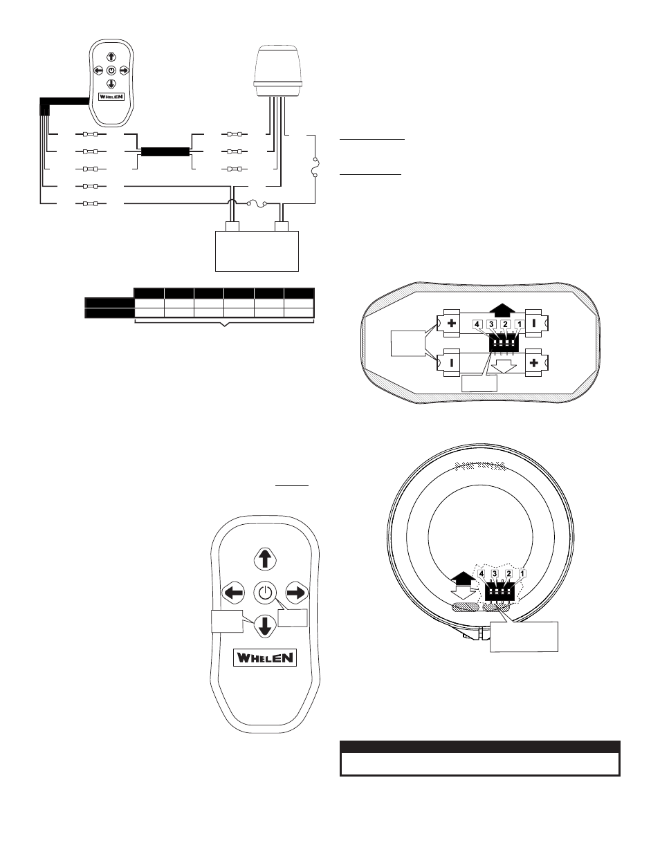
Wiring Diagram
(wired model)
(+)
Battery
(-)
Fuse
(3A)
Fuse
(10A)
RED
BLU
BLU
BLU
GRY
GRY
SHIELD
SHIELD
SHIELD
SHIELD
RED
Remote
Control
BLU
Maximum Recommended Wire Length (in Feet)
Current
Draw
Wire Gauge (AWG)
DIP4
Remote Control
Wireless
ON
OFF
BOTTOM-INSIDE VIEW
DIP
Switches
AAA
Batteries
(QTY 2)
Beacon
Wireless with dome removed
FRONT
RIGHT
LEFT
REAR
TOP VIEW
DIP4
DIP Switches are
located beneath the
dome inside this
opening.
ON
OFF
Wiring:
IN STANDARD MODELS there are 5 wires exiting the controller and 5
wires exiting the beacon. Connect these wires as shown in the wiring
diagram. Butt splices are included in the mounting kit. There is also a 2
conductor cable included (see wiring diagram)
IN WIRELESS MODELS, extend the RED (+) beacon wire to the positive
terminal of the battery (Fuse @ 10 AMPS) and the BLACK
(-) beacon wire to the ground terminal of the battery.
WARNING: All customer supplied wires that connect to the
positive terminal of the battery must be sized to supply at
least 125% of the maximum operating current and FUSED at
the battery to carry that load. DO
NOT USE CIRCUIT BREAKERS
WITH THIS PRODUCT!
Operation:
• Press the center switch to turn the
beacon on or off.
• When the beacon is switched off, it
will go through an orientation
sequence for approximately 30
seconds. When completed, the light
will be facing forward.
Battery Replacement:
The wireless remote control uses two (2)
AAA batteries. To replace the batteries,
remove the battery cover, secured with 2
screws, from the remote control. Install
the new batteries in the orientation
shown and reinstall the battery cover.
CAUTION! DO NOT LOOK DIRECTLY AT THESE LEDS WHILE THEY ARE ON.
MOMENTARY BLINDNESS AND/OR EYE DAMAGE COULD RESULT!
IMPORTANT WARNING!
Dip Switch Settings (Wireless models-only):
As shipped, the DIP switches are in the “OFF” position. In the event that
two or more Wireless Pan and Tilt Beacons are operating in close
proximity, interference may occur. In this situation, changing one of the
beacons operating frequency should alleviate any interference. Note that
the switches on both the beacon and remote must be set identically.
To Change Operating Frequency:
On the Remote: Remove the back cover (2 screws) and remove the
Batteries. Set the DIP switches to a new setting. NOTE: Do NOT set all
the dip switches to ON.
On the Beacon: Remove the screw from the clamp ring and remove the
dome (be careful not to damage the o-ring). Set the DIP switches to a new
setting.NOTE: Do NOT set all the dip switches to ON.
Replace the batteries in the remote and test the beacon to confirm normal
beacon operation without interference. If the Beacon operates properly,
replace the back cover on the remote and reassemble the beacon dome.
Be careful not to damage the O-Ring during reassembly.
Remote Control
Wired & Wireless
UP
RIGHT
LEFT
DOWN
ON-OFF
TOP VIEW
ON-OFF
Switch
TOP VIEW OF
CONTROLLER
Light
direction
control
Specifications:
RANGE: 200 Ft. Line of sight (wireless remote)
Operation Frequency: 915 MHZ ISM BAND: 902.0 MHZ to 928.0 MHZ.
(wireless remote)
Power: 12 Volts DC 5 AMPS MAX.