Wiring, Page 3, Red/wht yel/grn – Whelen TAFR03 User Manual
Page 3: Wire, Wire connections / power cable, Wire connections / control cable
Page 3
Arrow ground
Arrow ground
Arrow positive
Arrow positive
+12 VDC (switched)
+12 VDC (switched)
+12 VDC (switched)
+12 VDC (switched)
RED/WHT
YEL/GRN
BATTERY
PA
1
D1
D2
D3
D4
P1
P2
P3
PA
2
PA
3
PA
4
P4
DA1
DA2
DA3
DA4
BLK/WHT
BLUE
WHT/BLK
RED
WHITE
BLACK
BROWN
+12 VDC
+12 VDC - Right Arrow
+12 VDC
+12 VDC - Left Arrow
Ground
+12VDC - Flash (Middle)
Ground
+12VDC Low Power
No Connection
15 Amps
1 Amp
SPST SWITCH
1 Amp
SPST SWITCH
1 Amp
SPST SWITCH
1 Amp
SPST SWITCH
WIRE
(power cable)
BLACK
BLK/WHT
RED
RED/WHT
Connect to vehicle ground
Connect to vehicle ground
Connect to +12 VDC
Connect to +12 VDC
WIRE
(control cable)
WHITE
YEL/GRN
BROWN
BLUE
Apply positive voltage to activate the RIGHT arrow
Apply positive voltage to activate the LEFT arrow
Apply positive voltage to activate the CENTER (flashing)
Apply positive voltage to switch the arrow into LOW POWER
Applying positive voltage to the BLUE wire
puts the arrow into low power until voltage is removed.
Low Power:
WARNING: All customer supplied wires that connect to the positive terminal of the battery must be
sized to supply at least 125% of the maximum operating current and FUSED at the battery to carry
that load. DO NOT USE CIRCUIT BREAKERS WITH THIS PRODUCT!
SPLIT ARROW:
Applying positive voltage
to the WHT & YEL/GRN
wires simultaneously will
activate
.
Split Arrow
0 1 - 0 6 8 7 5 1 0 - 0 1 FLEET RACK, TRAFFIC ARROW, SILVERADO
SUB ASSY, 10 OUTLET T/A MODULE FLT-RACK ARROW
1
0 1 - 0 2 6 E 8 3 5 - 0 0
SUB ASSY, ION LT AMBER 2-WIRE BLACK HSG
16
0 1 - 0 2 6 D 8 1 6 - 1 0
ENDCAP, 2" SQUARE FLEET-RACK
2
11 - 2 6 D 9 2 1 - 0 0 0
CVR, 3RD BRAKE LT CUT-OUT TRAFC ADV. FLT-RACK BLK
1
11 - 2 6 E 3 6 7 - 0 0 7
SCREW, 6-32 X 1/2 PPHMS SS BLACK OXIDE VIBRA-TITE VC-3
4
1 4 - 0 6 2 2 1 C - 0 8 V
SCREW, 8 X 1/2 PPHSMS TYPE A SS BLK ZINC OXIDE
4
1 5 - 0 8 1 2 1 B - 0 8 2
HOUSING, 4 POS PLUG UNIVERSAL MATE-N-LOK
1
3 9 - 1 V 0 4 0 1 7 - 0 0
GROMMET, BODY MOUNT ION LIGHT
16
2 1 - 0 0 6 D 3 7 8 - 0 0
GROMMET, 1" SLIM LINE
5
2 1 - 11 2 6 3 2 0 4 - 0
GROMMET, #8
4
2 1 - 1 2 0 8 0 9 0 5 - 1
PLUG, RECTANGULAR TUBING
6
2 1 - 3 2 1 8 5 3 5 - 0 0
PLUG, DOME, 1/2" HOLE DIA DP500, BLK NYLON, 94V-2
5
2 1 - 3 7 1 8 4 2 5 - 0 5
PLUG, DOME, 1.0" HOLE DIA DP1000, BLK NYLON, 94V-2
6
2 1 - 3 7 1 8 4 2 5 - 1 0
PLUG, WIRE ACCESS FLEET-RACK
4
2 2 - 2 0 6 D 9 2 0 - 0 0
CLAMP, 7/16"
1
2 6 - 0 1 2 1 0 5 3 - 0 1
CLIP, CHRISTMAS TREE
CABLE POWER TRAFFIC ARROW FLEET-RACK
CABLE CONTROL TRAFFIC ARROW FLEET-RACK
HARNESS INTERNAL DRIVER FLEET-RACK ARROW
HARNESS INTERNAL PASSNGR FLEET-RACK ARROW
8
2 6 - 1 5 1 8 4 4 3 - 0 0
1
4 6 - 0 7 4 6 9 3 1 - 0 0
1
4 6 - 0 7 4 6 9 3 2 - 0 0
1
4 6 - 0 7 8 7 5 1 9 - 0 0
1
4 6 - 0 7 8 7 5 1 9 - 0 1
0 1 - 0 6 8 7 5 1 0 - 0 2 FLEET RACK, TRAFFIC ARROW, SUPER DUTY
0 1 - 0 6 8 7 5 1 0 - 0 3 FLEET RACK, TRAFFIC ARROW, F150
1
16
2
1
4
4
1
16
5
4
6
5
6
4
1
8
1
1
1
1
1
16
2
1
4
4
1
16
5
4
6
5
6
4
1
8
1
1
1
1
FRAME, MAIN SILVERADO/F-150 W-LOGO FLT-RCK ARW
FRAME, MAIN SUPR DUTY
FLT-RACK ARROW
W-LOGO
1
0 6 - 2 6 E 8 4 7 - 0 0 1
0 6 - 2 6 E 8 4 7 - 0 0 2
1
1
KIT, MTG BRACKET SILVERADO/SUPER DUTY FLEET-RACK
KIT, MTG BRACKET F-150 FLEET-RACK
1
0 1 - 0 4 6 D 9 9 2 - 0 1
0 1 - 0 4 6 D 9 9 2 - 0 2
1
1
SEAL, INTERFACE 4 POS UNIVERSAL MATE-N-LOK
1
3 9 - 1 V 1 7 2 6 9 - 0 0
1
1
SEAL, WIRE 4 POS UNIVERSAL MATE-N-LOK
1
3 9 - 1 V 1 7 2 6 9 - 0 1
1
1
0 1 - 0 6 8 7 5 1 0 - 0 4 FLEET RACK, TRAFFIC ARROW, UTILITY BODY
1
16
2
1
4
4
1
16
5
4
6
5
6
4
1
8
1
1
1
1
1
1
1
1
0 6 - 2 6 E 8 4 7 - 0 0 3 FRAME, MAIN UTIL BODY W-LOGO FLEET-RACK ARROW
KIT, MTG BRACKET, UTILITY BODY FLEET-RACK
0 1 - 0 4 8 7 5 9 3 - 0 1
2
3
ITEM
PART NUMBER
DESCRIPTION
QTY QTY QTY QTY
11
12
13
14
15
16
17
18
19
20
4
5
6
7
8
9
10
1
21
22
23
24
25
26
27
28
28
1
5
11
2
6
3
9
12
21 22 27
4
14
8
10
13
24
23
24
23
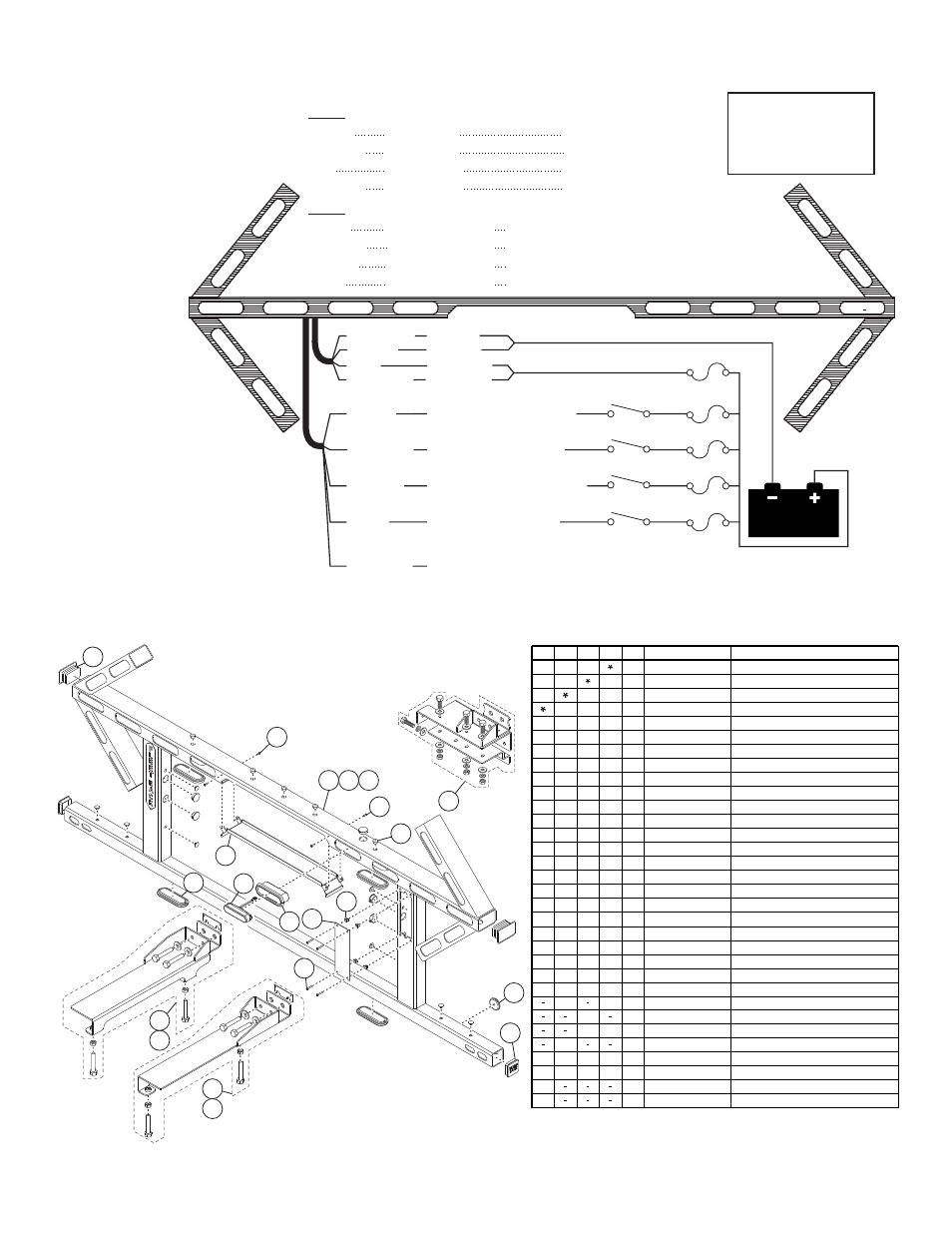
Wiring:
Wire Connections / Power Cable:
1.
Splice the RED and RED/WHT wires
together, then extend this single wire
to the battery and install a 15 amp
fuse block (customer supplied) to
the end of the wire. Remove the
fuse before connecting any
wires to the battery.
Connect the wire to the
POSITIVE (+) battery
terminal.
IMPORTANT: There
must not be more
than 2 feet of wire
between fuse block
and battery. The
wire between fuse and
battery is unprotected,
do not allow this wire to
come in contact with any
other wires.
2.
Splice the BLACK and BLK/WHT
wires together, then extend this single
wire to the battery and connect it to the
battery ground. If your vehicle has a
cable extending from the negative
terminal of the battery to the chassis, it
is best to attach the black wire at the
chassis connection.
Wire Connections / Control Cable:
Extend the WHITE, YELLOW/GREEN, BROWN and BLUE wires to the battery. Fuse each wire a 1 amp and install an SPST switch on each wire. All
fuses and switches are customer supplied.