Fig. 1 flasher, Flasher connection & operation, Hi/low power – Whelen DOT3401A User Manual
Page 2: Scan-lock, Mounting the flasher
Page 2
DOT-LED®: Included are two, 10-12 gauge and
twenty four, 14-16 gauge Faston connectors to
connect your lighting options to the flasher and to
connect your power wires.
WARNING! All customer supplied wires that
connect to the positive terminal of the battery
must be sized to supply at least 125% of the
maximum operating current and FUSED at the
battery to carry that load. DO NOT USE CIRCUIT
BREAKERS WITH THIS PRODUCT!
IMPORTANT! Before returning the vehicle to
active service, visually confirm the proper
operation of this product, as well as all vehicle
components/equipment
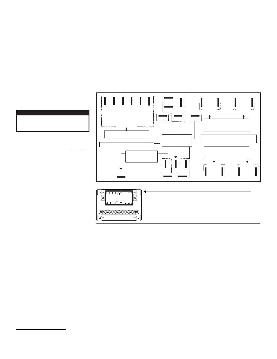
Flasher Connection & Operation:
Connect your lighting options (Lightheads, beacons
etc...) to the flasher as shown. Connect the positive
wire of the lighting option to outputs 1 thru 8
(Each outlet will handle 5 AMPS PEAK). Connect
the negative wires of your lighting options to any of
the ground terminals. All terminals take a Faston
connector (supplied). Applying +12V DC to the
positive wire will activate its outlet or function (See
wiring diagram).
NOTE: Keep in mind that each control wire
activates two outlets each. Be sure to connect
lights that need to be on the same circuit accordingly, such as 2 front lightheads or both rear options would be. Fuse the control wires at 1 AMP each.
Hi/Low Power:
This feature allows the user to step the unit down to low power operation for nighttime use
Option 1 / Latching Mode: By applying +12V DC to the "Hi/Low Power Control Wire” for less than 1 second, the system is latched into low power operation. The unit
must be turned off and then back on to restore normal high power (Momentary Switch).
Option 2 / Level Mode: Applying +12V DC to the "Hi/Low Power Control Wire” for more than 1 second holds the system in low power until the voltage is removed
(Toggle Switch).
Photocell (optional): If you have the photocell option, plug the BLACK wire into the negative photocell terminal, the RED wire into the positive photocell terminal and
the VIOLET wire into the low power terminal of the flasher (see wiring diagram). With the photocell hooked up, the system will switch to low power automatically at
night. Mount the photocell where it will be exposed to daylight, away from any vehicle lighting.
Scan-Lock™:
Scan-Lock allows the user to choose from several flash patterns. The entire system will display the pattern you choose (All outputs will display the same pattern).
TO CYCLE FORWARD THROUGH FLASH PATTERNS: Activate any of the outputs by applying power. With the outputs activated apply +VBAT to the Scan-Lock wire
for less than 1 second and release. Repeat to advance to next pattern.
TO CHOOSE A PATTERN: While cycling through the available flash patterns allowing a pattern to run for at least 5 seconds will configure it as the default pattern.
Now when activated the entire system will display this flash pattern.
TO RESET TO THE FACTORY DEFAULT PATTERN: Turn off all functions. Apply +VBAT to the Scan-lock wire while turning any of the functions back on. The system
is now restored to its factory default pattern.
Available Flash Patterns: 1 - SignalAlert™ Outputs 1, 2, 3 & 4 alternate with 5, 6, 7 & 8 > 2 - SignalAlert™ Outputs 1, 3, 5 & 7 alternate with 2, 4, 6 & 8 > 3 -
SignalAlert™ All outputs flash simultaneously > 4 - CometFlash® 75 Outputs 1, 2, 3 & 4 alternate with 5, 6, 7 & 8 > 5 - CometFlash® 75 Outputs 1, 3, 5 & 7 Alternate
with 2, 4, 6 & 8 > 6 - CometFlash® 75 All outputs flash simultaneously.
Available SSNF Flash Patterns: (Outputs 1, 2, 3 & 4 display CometFlash® and Outputs 5, 6, 7 & 8 display SingleFlash) 7 - SSNF: Outputs 1, 2, 7 & 8 alternate
with 3, 4, 5 & 6 > 8 - SSNF: Outputs 1, 4, 5 & 8 alternate with 2, 3, 6 & 7 > 9 - SSNF: All outputs flash simultaneously
CAUTION! DO NOT LOOK DIRECTLY AT
THESE LED’S WHILE THEY ARE ON.
MOMENTARY BLINDNESS AND/OR EYE
DAMAGE COULD RESULT!
IMPORTANT WARNING!
Mounting the Flasher:
One of the most common places chosen is against the rear wall of the cab. This is a good choice for several reasons, such
as good air circulation and heat dissipation.
• The flasher is not waterproof. The mounting area must be dry and free from elements that could damage the unit (road salt, sand, snow).
• The flasher should not be exposed to excessive heat.
• The mounting area should be easily accessible for wiring and service purposes.
• Mounting the flasher to a metal surface is recommended for optimum heat dissipation.
• Be sure that the backside of the proposed mounting surface does not hide any wires, cables, fuel lines, etc., that could be damaged by
drilling the mounting holes.
• Select a location towards the middle of the cab.
• Be sure that the mounting location is a minimum of 8” from the cab floor.
• The flasher should be mounted on as flat a surface as possible.
GND
GND
GND
GND
GND
GND
GND
GND
Connect to the Negative
Battery Terminal
(-)
Plug Positive (+) wires from lighting
options into the output terminals.
MAXIMUM 5 AMPS PEAK EACH OUTPUT
Plug Negative (-) wires
from lighting options
into the GND terminals.
These terminals are to be
used for connecting the
optional Photocell.
(-) BAT
Photocell (+)
Photocell (-)
Scan-Lock
Low Power
Outputs
1&2
Outputs
3&4
Outputs
5&6
Outputs
7&8
Outputs
3&4
4
6
1
7
2
8
3
5
Outputs
7&8
Outputs
1&2
Outputs
5&6
Control Wires
(+) BAT
Connect to user supplied switches.
Fuse each control wire @ 1 AMP.
IMPORTANT: Outputs 1 thru 8 will handle a maximum of 5 AMPS Peak each.
IMPORTANT! Do NOT mount the Junction Box where it could be
exposed to moisture. The recommended mounting location
is within the passenger compartment.
Fig. 1 Flasher
WARNING: All Customer supplied wires that connect to the positive terminal of the battery
must be sized to supply at least 125% of the maximum operating current and fused "at the
battery" to carry that load. DO NOT USE CIRCUIT BREAKERS WITH THIS PRODUCT!
Plug Positive (+) wires from lighting
options into the output terminals.
Connect to the Positive (+) Battery Terminal
Fuse @ 25 AMPS.
MAXIMUM 5 AMPS PEAK EACH OUTPUT
- DOT3401B DOT3401D DOT3501A DOT3501B DOT3501D DOT3701A DOT3701B DOT3701D DOT3402A DOT3402B DOT3402D DOT3502A DOT3502B DOT3502D DOT3702A DOT3702B DOT3702D DOT3103 DOT3705D DOT3705B DOT3705A DOT3505D DOT3505B DOT3505A DOT3405D DOT3405B DOT3405A DOT3704D DOT3704B DOT3704A DOT3504D DOT3504B DOT3504A DOT3404D DOT3404B DOT3404A DOT3109 DOT3406A DOT3406B DOT3406D DOT3506A DOT3506B DOT3506D DOT3706A DOT3706B DOT3706D DOT3107 DOT3108 DOT3410A DOT3410B DOT3410D DOT3510A DOT3510B DOT3510D DOT3710A DOT3710B DOT3710D