Rear housing assembl y, 400 series, 700 series – Whelen DOT3401A User Manual
Page 5: 500 series, Page 5, Side view
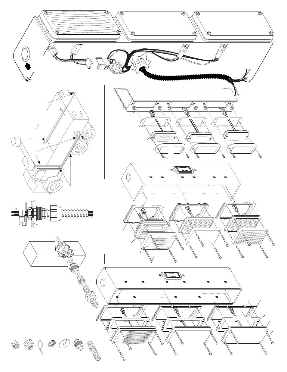
Page 5
3.
RUN
BACK
A
LONG
FRAME
RAIL,
INT
O
C
AB
AND
H
OOK
T
O
FLASHER
(SAME
FOR
O
THER
SIDE)
1.
RUN
WIRE
F
ROM
,
DOWN
FRONT
A
ND
ALONG
UNDERSIDE
O
F
DUMP
B
ODY
T
O
H
INGE
POINT
.
.
.
LIGHTS
2.
A
T
THE
H
INGE
POINT
,
LEA
V
E
A
1
2
INCH
SER
VICE
LOOP
RUN
WIRE
F
ROM
D
OWN
DUMP
BODY
,
A
LONG
FRAME
RAILS,
T
O
FLASHER.
REMOTE
HEAD
(SAME
INST
ALLA
TION
F
OR
OTHER
S
IDE)
DUMP
H
INGE
POINT
Locking
Fixture
Locking
Cuff
Flex
T
ube
T
y
-W
rap
Locking
Nut
Primary
Shaft
Housing
Plastic
W
asher
Flex T
ube
Assembly:
1.
2.
3.
4.
5.
6.
7.
8.
9.
Insert the harness cables into the flex tube.
Be sure there is enough length of cable
pulled through the other end of the flex tube.
Fit the locking cuf
f onto the flex tube.
Slide the locking fixture onto the cables.
Slide the primary shaft housing onto the cables.
Position the locking fixture inside the primary
shaft housing.
Fit the flex tube completely around the end
of the primary shaft housing.
T
ighten the locking cuf
f around the primary
shaft housing.
Insert the harness-flex tube assy
. through
the wire opening in the remote head.
Secure the assembly with the locking
nut and install plastic washer and
T
y-wrap
for strain relief then tighten securely
.
White plastic
washer
and
Ty-wraps
for
strain
relief
Housing
Cable
Cable
SIDE
VIEW
6 X 1-1/2"
PPHSMS
TRIPLE HOUSING
400 OPTIC
LENS
400 SERIES
LIGHTHEAD
MOUNTING F
ACE PLA
TE
400 SERIES
IMPORT
ANT! Rear housings should be mounted in a full upright, vertical position
BACK PLA
TE
MOUNTING F
ACEPLA
TE
#6 X 1/2" PPHSMS
700 SERIES LIGHTHEAD
700 SERIES
REAR HOUSING
ASSEMBL
Y
:
FLANGE
500
SERIES
LIGHTHEAD
GASKET
GROMMET
TRIPLE HOUSING
500 SERIES
#10 X 3/4"
PPHSMS
IMPORT
ANT
:ALL
CAPS
MUST BE INST
ALLED IN
UNUSED HOLES.
- DOT3401B DOT3401D DOT3501A DOT3501B DOT3501D DOT3701A DOT3701B DOT3701D DOT3402A DOT3402B DOT3402D DOT3502A DOT3502B DOT3502D DOT3702A DOT3702B DOT3702D DOT3103 DOT3705D DOT3705B DOT3705A DOT3505D DOT3505B DOT3505A DOT3405D DOT3405B DOT3405A DOT3704D DOT3704B DOT3704A DOT3504D DOT3504B DOT3504A DOT3404D DOT3404B DOT3404A DOT3109 DOT3406A DOT3406B DOT3406D DOT3506A DOT3506B DOT3506D DOT3706A DOT3706B DOT3706D DOT3107 DOT3108 DOT3410A DOT3410B DOT3410D DOT3510A DOT3510B DOT3510D DOT3710A DOT3710B DOT3710D