Fig. 2, Fig. 1, Read before installing – Whelen WPA1 User Manual
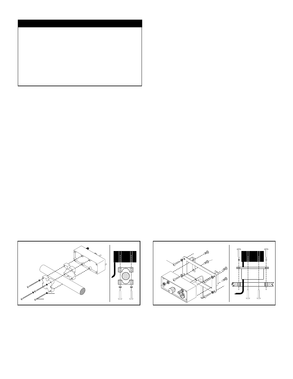
Page 3: Flush mount: (fig. 2)
Page 3
#6 Sheet
Metal
Screw
#6 Sheet
Metal
Screw
Fig. 2
Flush Mount
FRONT
TO
P
Handle Bar Mount
#6 Sheet Metal Screw
Lockwasher
Fig. 1
FRONT
TO
P
READ BEFORE INSTALLING!!!
Do not install this product or route any wires in the deployment
area of your air bag. Equipment mounted or located in
the air bag deployment area will damage or reduce the
effectiveness of the air bag or become a projectile that could
cause serious personal injury or death. Refer to your vehicle
owner's manual for the air bag deployment area.
The User/Installer assumes full responsibility to determine the
proper mounting location, based on providing ultimate safety
to all passengers inside the vehicle. Whelen Engineering Co.
assumes no liability or responsibility for determining individual
applications or exact installation location criteria.
This manual outlines installation procedures for the WPA
TM
and
BETA
TM
Series Control Head (Models WPA1
TM
, WPA2
TM
and
BETA2
TM
). The WPA
TM
Series Control Head was designed for
automotive, motorcycle and marine applications. Read this
manual carefully before beginning the installation.
Section I: Motorcycle Applications
For motorcycle applications, a special handlebar mounting
bracket has been provided. Both the bracket and the control
head mounting holes have been designed to allow the WPA1
TM
to be positioned in any of the following ways: centered on the
bracket, off-set to the left of bracket, off-set to the right of the
bracket or vertical to the bracket.
Mounting the WPA1™ Series Control Head
Handlebar Mount: (Fig. 1)
1.
Locate a suitable mounting location for the WPA1. Any
open space on the handlebars will be acceptable, provided
the control head or bracket does not interfere with any
motorcycle components or steering operations.
2.
Position the bracket around the handlebar on the mounting
location. Now place a #6 internal-tooth lockwasher
(provided) onto a #6 x 2” sheet metal screw (provided) and
insert through brackets and into the back of the control
head (Fig. 1). Secure unit to handlebar and tighten firmly.
Section II: Automotive & Marine Applications
The WPA2 & BETA2 Control Heads (the “WPA Series”) can be
mounted in four different styles: a flush mount and 3 surface
mounts (Figures 2 through 5). Flush mounting (Figure 2),
requires a special bracket (included with the WPA2 and
available for the BETA2
&
WPA1). Surface mounting uses the
hardware included with your WPA1 Series Control Head.
CAUTION! Mounting will require cutting and drilling, it is
absolutely necessary to make sure that no vehicle components
could be damaged by the mounting process. Check both sides
of the mounting surface and if damage is possible, select a
different mounting location.
Flush Mount: (Fig. 2)
1.
Locate a suitable mounting location for the control head. Be
sure that the control head will fit properly and not interfere
with any vehicle components.
2.
Position the flush mount bracket (BETA2BKT) onto the
proposed mounting location to use as a template. Using an
awl or other suitable tool, scribe the guide lines (from which
you will cut the opening) onto the mounting surface where
the bracket is to go.
3.
Carefully cut the opening into the mounting location.
4.
Secure the control head to the bracket. Using the supplied
sheet metal screws.
5.
Slide the control head (with bracket attached) into the
mounting hole you cut
6.
Drill the screw holes, with an appropriately sized drill bit.
7.
Using the supplied sheet metal screws, secure the control
head / bracket to the mounting surface.