Mounting, Wiring, Operation – Whelen M4B6R User Manual
Page 2
Page 2
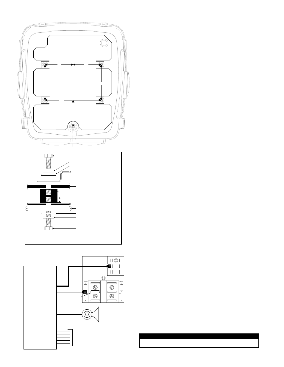
Mounting Hole Locations
4.75”
6.37”
6.37”
10”
5”
5”
CL
1/4-20 x 3/4” Hex Head Bolt
Flat Washer
Internal Tooth Lockwasher
Power Box (bottom)
Vibration Dampener
0.375”
Mounting Plate
Note: Maximum bolt depth!
Internal Mounting Plate
Luggage Rack Tubing
Do not thread this bolt more than 0.375” into the vibration dampener!
Different hardware may be needed to ensure both proper mounting
and compliance with this requirement.
*
1/4-20 x 1 ½” Hex Head Bolt*
Internal Tooth Lockwasher
Flat Washer
Siren
Speaker
Fuse Block
To Customer Supplied Switches
(refer to the manual included
with your particular siren
amplifier for wiring information
and fusing)
FUSE
Fuse per
amplifier
manual
Siren Amplifier
(optional)
Siren Amplifier / Optional
Mounting:
This box requires a mounting plate secured to the motorcycle’s luggage rack. If the bike is not
equipped with a mounting plate, one must be fabricated prior to installation of this box. Five
mounting holes (.281” dia.) are required to mount this box.
If the motorcycle is already equipped with a mounting plate, it may be necessary to drill the 5
mounting holes required for this installation.
Use the diagram shown to determine the precise location of these holes.
1.
Position the box onto the mounting plate. Align the 5 vibration dampeners with the 5
mounting holes in the mounting plate.
2.
Using the illustrations shown, secure the box to the mounting plate using the provided
hardware.
NOTE: Your luggage rack may already have the correct mounting holes drilled. Check
the measurements below and if these holes already exist at the proper distance,
remove any existing mounting hardware from the holes and secure the box with the
supplied mounting hardware.
3.
Place the box into its mounting position on the deck and secure it with the
supplied mounting hardware as shown in the diagram.
Wiring:
Diagrams for optional equipment are shown below and on the following page. Refer to the
diagram(s) on the following page for general motorcycle box wiring information.
WARNING: All customer supplied wires that connect to the positive terminal of the
battery must be sized to supply at least 125% of the maximum operating current and be
FUSED at the battery to carry the load. DO NOT USE CIRCUIT BREAKERS WITH THIS
PRODUCT!
Operation:
Flash Pattern Selection: Lights must be switched on to use Scan-Lock™
TO CYCLE THROUGH ALL PATTERNS: Apply +12 volts to the WHT/VIO wire for less than 1
second and release to cycle forward. Apply +12 volts to the WHT/VIO wire for over 1 second
and release to cycle backward.
TO SET A PATTERN AS DEFAULT: When the desired pattern is displayed, allow it to run for
more than 5 seconds. The lighthead will now display this pattern when active.
TO RESET TO THE FACTORY DEFAULT PATTERN: Turn off power, apply +12 volts to the
WHT/VIO wire, then turn power on.
Note: If the installer wishes to connect the pattern selection wire (WHT/VIO) to a switch,
a momentary switch (normally open) is recommended.
Outlet Activation:
Apply +12VDC to a control wire(s) to activate the outlet. The outlet(s) remain active until
voltage is removed. Note: This flasher uses low current switching (100mA per control wire)
Low Power Operation:
Apply +12VDC to the VIO wire for Low Power Operation. Low Power Operation will remain in
effect until voltage is removed from the VIO wire. An SP/ST switch is recommended.
Flash Pattern Phase Modes:
The flasher used in this application has 3 different phase modes. Each pattern is available in
each mode. Each mode effects the relationship between each outlet: Phase 1 - 1, 3, 5 & 7
alternate with 2, 4, 6 & 8 Phase 2 - 1, 2, 3 & 4 alternate with 5, 6, 7 & 8 Phase 3 - All flash
simultaneously
Available Flash Patterns:
1. SignalAlert™ (Phase 1)
2. SignalAlert™ (Phase 2)
3. Signal Alert™ (Phase 3)
4. CometFlash® (Phase 1)
5. CometFlash® (Phase 2)
6. CometFlash® (Phase 3)
7. SingleFlash 75 (Phase 1)
8. SingleFlash 75 (Phase 2)
9. SingleFlash 75 (Phase 3)
10. SingleFlash 150 (Phase 1)
11. SingleFlash 150 (Phase 2)
12. SingleFlash 150 (Phase 3)
13. SingleFlash 375 (Phase 1)
14. SingleFlash 375 (Phase 2)
15. SingleFlash 375 (Phase 3)
16. DoubleFlash 75 (Phase 1)
17. DoubleFlash 75 (Phase 2)
18. DoubleFlash 75 (Phase 3)
19. ModuFlash™ (Phase 1)
20. ModuFlash™ (Phase 2)
21. ModuFlash™ (Phase 3)
22. ActionFlash™ (Phase 1)
23. ActionFlash™ (Phase 2)
24. ActionFlash™ (Phase 3)
25. ActionScan™ (Phase 1)
26. ActionScan™ (Phase 2)
27. ActionScan™ (Phase 3)
28. Invalid Pattern For This Application.
Do Not Use.
CAUTION! DO NOT LOOK DIRECTLY AT THESE LED’S WHILE THEY ARE ON.
MOMENTARY BLINDNESS AND/OR EYE DAMAGE COULD RESULT!
I M P O R TA N T W A R N I N G !