Wiring diagram, Optional equipment, Page 3 – Whelen M4B6R User Manual
Page 3: Charger system, 6 light / m4 led
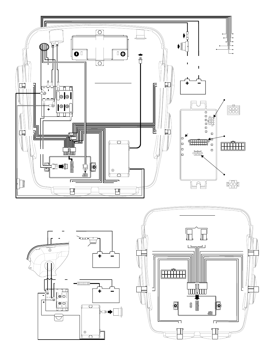
Page 3
CHARGER
POWER CONNECTOR
CHARGER INLET
15A/120 VAC
POWER
CONNECTOR
POWER
CONNECTOR
BUTT SPLICE
FUSE BLOCK
40 AMP FUSE
CUSTOMER
S U P P L I E D
FUSE BLOCK
3 AMP FUSE
WIRE COVER
12V BATTERY
Customer Supplied
12V BATTERY
+ 12 VOLTS DC
RED
BLACK GROUND
+ 12 VOLTS DC
RED
BLACK GROUND
BRAKE/TAIL/TURN
HARNESS
FLASHER CONTROL
WIRES
YEL / LEFT TURN
WHT / GROUND
GRN / RIGHT TURN
BRN / TAIL
RED / BRAKE
WHT/VIO / SCANLOCK
YEL / OUTLETS 7 & 8
ORG / OUTLETS 5 & 6
BRN / OUTLETS 1 & 2
RED / OUTLETS 3 & 4
VIO / LOW POWER
FUSE BLOCK NOTE:
Max. current draw per
circuit = 15A
(Fuse circuit @ 125%
of max. current draw)
Wiring Diagram
6 Light / M4 Split-LED
Wiring Diagram
6 Light / M4 LED
CHARGER
INLET
15A/120
VAC
POWER CONNECTOR
BUTT
SPLICE
40
AMP
FUSE
12V BATTERY
Customer Supplied
+1
2V
D
C
RED
BLACK
GND
P1
P4
P5
2-
BLK
2-
BLK
3-
GRN
3-
RED
1-
RED
1-
GRN
P7
2 - BLK
1 - YEL
3 - ORG
P6
3 - YEL
1 - ORG
2 - BLK
P3
1
-BRN
3
-BLU
2
-BLK
P2
3-V
IO
1-G
RY
2
-BLK
CHARGER
Fuse
Block
12V BATTERY
2
1
RED
BLK
FUSE
BLOCK
3
AMP
FUSE
POS
NEG
10
AMP
10
AMP
Optional (See "Charger System" Above)
Optional
BTT
/GND
/WHT
1 - WHT/VIO /
2 - VIO /
3 - BRN /
4 - RED /
5 - ORG /
6 - YEL /
-
™
Low Power
Scan Lock
Outlets 1&2
Outlets 3&4
Outlets 5&6
Outlets 7&8
1
2
3
6 5 4
1 - BLU
2 - GRY
3 - BLK
4 - BLK
5 - N/C
6 - BLK
7 - BRN
8 - ORG
9 - GRN
10 - VIO
11 - BLK
12 - N/C
13 - BLK
14- BLK
15 - RED
16 - YEL
8
1
16
9
10
11
12
13
14
15
2
3
4
5
6
7
4
13
6
1
8
1
7
2
6
3
5
4
2
Lighthead Connector
(Rear View)
Output
Indicators
Flasher Control Connector
(Rear View)
1
2
- +12VDC (RED)
Fuse @ 10 Amp
- Ground (BLK)
-
1 2
Power Connector
(Rear View)
FLASHER
Optional Equipment:
Charger System:
Optional
Apply +12VDC to a control wire
to activate the outlet. The outlet
remains active until voltage is removed.
Note: This flasher uses low current
switching (100mA per control wire)
P1
P9
BLK
YEL
P7
BLK
RED
P8
BLK
ORG
P6
BLK
GRN
P4
BLK
BRN
P2
BLK
GR
Y
NOT USED
P5
BLK BLU
P3
BLK VIO
1 - BLU
2 - GRY
3 - BLK
4 - BLK
5 - BLK
6 - BLK
7 - BRN
8 - ORG
9 - GRN
10 - VIO
11 - BLK
12 - BLK
13 - BLK
14- BLK
15 - RED
16 - YEL
8
1
16
9
10
11
12
13
14
15
2
3
4
5
6
7
Lighthead Connector
(Rear View)