Model pccs9rw, Mounting, Wiring – Whelen PCCS9RW User Manual
Page 2: Programming the pccs9rw, Load, Battery
Page 2
®
Screw
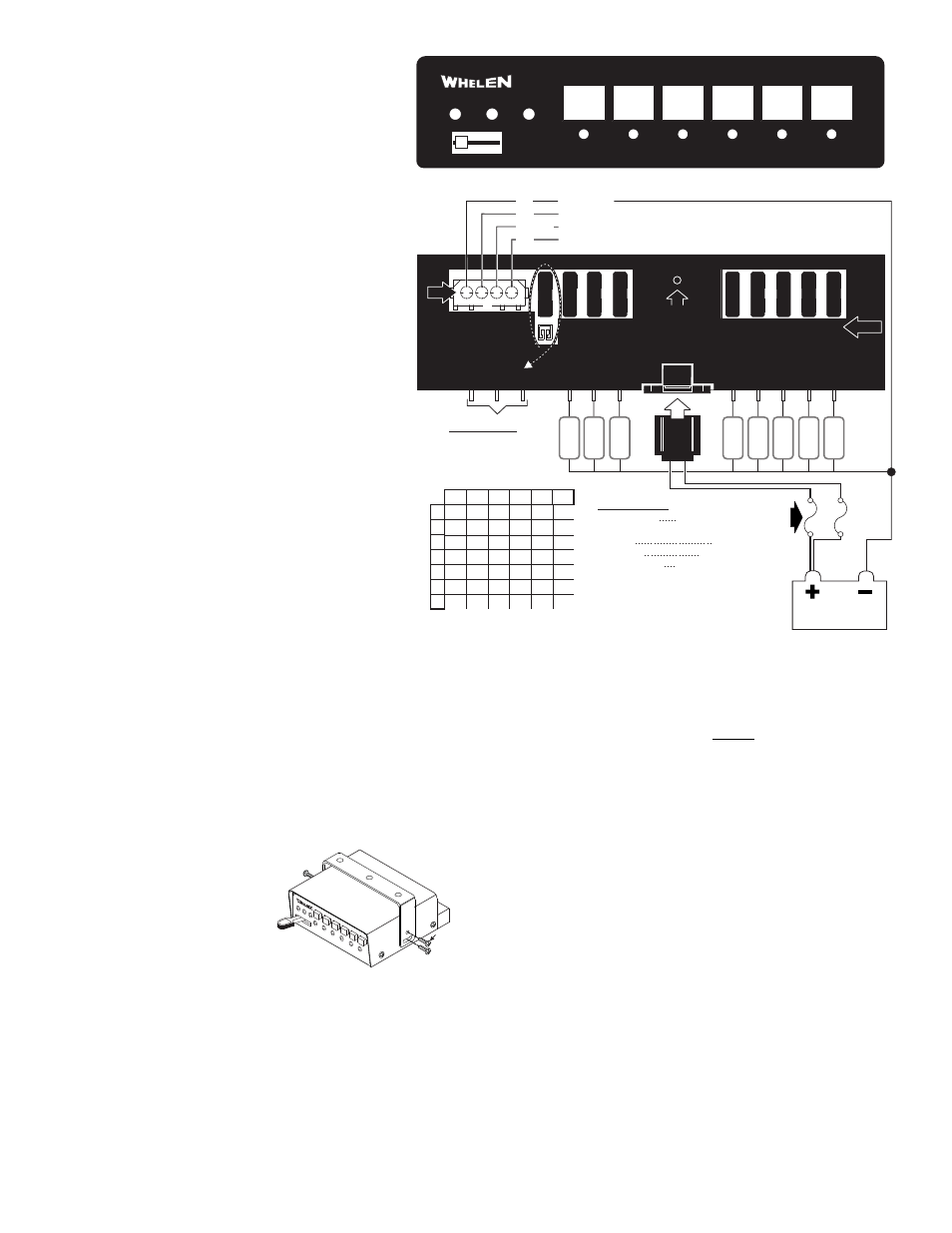
PCCS9RW REAR VIEW
20A
20A
20A
20A
20A
20A
20A
20A
20A
To +12 volt. Ignition activated switch
SIREN Enable
INPUT: To PIN 2 of J3 on Primary Unit when copying from other PCCS9RW
(Cap GREY wire when not in use)
RED
WHT/GRN
GRY
3 2 1
16.5
12.5
10
8
7
26
19.5
15.5
13
11
41.5
31
25
20.5
17.5
66
49.5
39.5
33
28
104
78.5
63
52.5
45
6
10 15.5 24.5 39
30
40
50
60
70
10
8
6
4
2
80
24.5 39
62 98.5 157
20
10.5
7.5
6
5
4.5
4
12
15.5
Wire Gauge / AWG
Current Draw /
AMPS
Distance is shown in feet.
GROUND
Refer to the wire gauge chart for the recommended wire size for your application.
Custom Fuse Configurations:
Push-Buttons 6 Functionality
See Section 8.2
®
1
1
OFF
4 WAY SWITCH
MOMENTARY PUSH BUTTON SWITCHES
PUSH BUTTON LED INDICATORS
PCCS9RW FRONT PANEL
2
2
6
5
4
3
3
(1)
(2)
(3)
O U T L E T S
O U T L E T S
O U T L E T S
J15 J14 J13
J12
J10
J11
J9
J8
J7
J6
J5
J4
J3
Fuse #
Scan-Lock™
switch
F1
F2
F3
F4
F5
F6
F7
F8
F9
PINS
4
BLK
LOAD
LOAD
LOAD
LOAD
LOAD
LOAD
LOAD
LOAD
Fuse @
40 AMPS
for each
wire.
(Fuse is
customer
supplied)
BATTERY
12.8 V +/- 20%
20ma
1.2 amps
12.8 V +/- 20%
20 AMPS/Outlet
80 AMPS Total Max
Input Current Logic:
Standby:
Operating:
Ouput Voltage:
Output Current:
Specifications:
Input Voltage:
Input Current Logic
Standby
Operating
Ouput Voltage
Output Current
Congratulations on selecting the PCCS9RW power
distribution control center. This unit offers a unique
collection of features designed to allow the user to
customize the operation to suit their individual needs.
Features include:
• Nine Programmable Power Distribution Switches (one 3
position slide switch, and 6 momentary switches).
• Nine 20 Amp relay controlled outputs.
• All switches can be programmed to activate any
combination of the relay outputs
• Any switch can be programmed to activate any other
momentary switch.
• Momentary switches can be programmed to be activated
as either a push on push off, momentary, flashing, or
timed output.
• Any switch can be programmed to activate siren enable
• LED Backlighting
• Copy one units configuration to another unit.
• Easy reset to Factory default settings
• Power Distribution fuses included
Model PCCS9RW
IMPORTANT: It is the responsibility of the installation
technician to make sure that the installation and operation
of this product will not interfere with or compromise the
operation or efficiency of any vehicle equipment! Before
returning the vehicle to active service, visually confirm the
proper operation of this product.
Mounting:
An aftermarket center console is recommended for the
mounting location of the PCCS9RW. This not only allows the
driver to reach the controls easily, but also keeps the unit safely
out of the path of the vehicle’s SRS air-bag. Follow the console
manufacturer’s instructions for mounting information. If a
console-type mount is not possible, the PCCS9RW includes a
bail strap mounting kit for over or under dash mounting.
WARNING: Regardless of the style selected, be sure to observe the
air-bag warning on the cover of this manual.
WARNING: Mounting this unit will require drilling. It is absolutely
necessary to make sure that no other vehicle components could be
damaged in the process. Check both sides of the mounting surface
before starting. If damage is likely, select a different location.
Bail Strap Mount:
1.
Position the bail strap in the selected
mounting location. Using an awl or
other suitable tool, scribe the
surface where the mounting holes
are to be drilled.
2.
Drill the mounting holes (using a
drill bit determined by the size of
the “customer supplied” mounting hardware
and the thickness of the mounting surface) and
secure the bail strap to the mounting location.
Console Mount:
Console manufacturers offer mounting kits that include all the necessary
hardware and brackets required to mount this unit into their console. The
console mount brackets are secured onto the unit the same way the bail
bracket is. Refer to the manual included with your console.
Function Labels: Take the supplied label kit and determine which label
describes the function of each switch. Peel the labels off the backing and
place them onto the switch buttons. Press the labels lightly into place.
Wiring:
WARNING! All customer supplied wires that connect to the positive
terminal of the battery must be sized to supply at least 125% of the
maximum operating current and be FUSED at the battery to carry
that load. DO NOT USE CIRCUIT BREAKERS WITH THIS PRODUCT!
Programming the PCCS9RW:
WARNING: Never try to program the PCC9RW while it is wired to the
vehicle. The unit must be removed from the vehicle before
programming. For programming, connect positive (+) 12 volts and
ground to J3 only.
The PCCS9RW switches include a slide switch and 6 momentary
switches. The slide switch has one off position and three active positions,
combined with the 6 momentary switches, makes a total of 9 switches.
For each of the 9 switches there are 9 corresponding relay outputs in the
back of the unit. The PCCS9RW has the capability of customizing how the
switches operate, and how they control the relay outputs as well as the
siren enable output.
Any of the 6 momentary switches can be configured to operate in one of
four switch types: push on push off, momentary, flashing, or timed output.
Any of the 9 switches can be configured to activate any combination of
relay outputs.
Any of the 9 switches can be configured to remotely activate any of the 6
momentary switches.
Any of the 9 switches can be configured to activate the siren enable
output.
One units configuration can be copied to another unit. The following
sections describe how to reconfigure the PCCS9RW.