8) terminal operation – Whelen PCCS9RW User Manual
Page 5
Page 5
®
Remove
screws
(4)
Access
fuse
here
2. Put the “SECONDARY” unit into “receive” mode:
• Place the SLIDE SWITCH in the OFF position and turn all Momentary
switches off.
• Press and hold the Scan-Lock™ switch.
• Press and release momentary switch 6.
• Release the Scan-Lock™ switch.
The GREEN, YELLOW and RED slide switch indicator light will turn
on for 2 seconds.
• When these indicator lights turn off press and release momentary
switch 1 on the “secondary” unit.
To confirm entry into this configuration mode: The GREEN slide
switch indicator light will turn on.
3. Put the “PRIMARY” unit into “transmit” mode.
• Place the SLIDE SWITCH in the OFF position and turn all Momentary
switches off.
• Press and hold the Scan-Lock™ switch.
• Press and release momentary switch 6.
•
Release the Scan-Lock™ switch.
The GREEN, YELLOW and RED slide switch indicator light will turn
on for 2 seconds.
• When these indicator lights turn off press and release momentary
switch 2.
To confirm entry into this configuration mode: The RED slide switch
indicator light will turn on.
4. Transfer the configuration.
• When the green indicator on the “secondary” unit turns off and the
yellow indicator turn on, proper communications has been established.
• Press and release momentary switch 1 on the “primary” unit to start the
transfer.
• When the green indicator on both the “primary and secondary” unit
turns on, the transfer is complete.
NOTE: If the RED slide switch indicator light on the “secondary” unit
turns on, an error has occurred, start back at step 1.
5. Store and activate the configuration.
• Press and release the Scan-Lock™ switch on both the “primary and
secondary” units.
All of the indicator lights will turn off and the data will be stored. This
will put both units back into normal operating mode.
OR...
• Turn the power off on both the “primary and secondary” units.
To transfer the configuration to another unit start back at step 1.
(8) Terminal Operation
8.1 Terminal Specifications
This PCCS9RW contains 11 outlets (Faston connectors) located on the rear panel.
They are designed to activate components that do not exceed specific current draw.
NOTE: It is important that any components connected to these terminals
do not exceed the maximum current rating for that terminal.
Warning! Total power distribution current is not to exceed 80 AMPS.
Outlet
Max. Load
Fuse
J4 . . . . . . 20 Amps . . . . . . . . . . . . . . . . . . . . . . . . . . . . . . . . . . . . . . . . . . . . F1
J5 . . . . . . 20 Amps . . . . . . . . . . . . . . . . . . . . . . . . . . . . . . . . . . . . . . . . . . . . F2
J6 . . . . . . 20 Amps . . . . . . . . . . . . . . . . . . . . . . . . . . . . . . . . . . . . . . . . . . . . F3
J7 . . . . . . 20 Amps . . . . . . . . . . . . . . . . . . . . . . . . . . . . . . . . . . . . . . . . . . . . F4
J8 . . . . . . 20 Amps . . . . . . . . . . . . . . . . . . . . . . . . . . . . . . . . . . . . . . . . . . . . F5
J10 . . . . . 20 Amps . . . . . . . . . . . . . . . . . . . . . . . . . . . . . . . . . . . . . . . . . . . . F6
J11 . . . . . 20 Amps . . . . . . . . . . . . . . . . . . . . . . . . . . . . . . . . . . . . . . . . . . . . F7
J12 . . . . . 20 Amps . . . . . . . . . . . . . . . . . . . . . . . . . . . . . . . . . . . . . . . . . . . . F8
J13 - J15 20 Amps (These outlets can not be activated simultaneously) . . . F9
The PCCS9RW factory default configuration terminal outputs are:
Slide Switch Positions:
Push-Button Switches:
0 = Outlets OFF
1 = Outlet J7 ON
1 = Outlet J4 ON
2 = Outlet J8 ON
2 = Outlets J4 & J5 ON
3 = Outlet J10 ON
3 = Outlets J4, J5 & J6 ON
3 =
Siren Enable Output ON
4 = Outlet J11 ON
3 = Factory Default:3 =
5 = Outlet J12 ON
3 = Siren Enable Output ON
6 = Outlets J13 - J15 (See section 8.2)
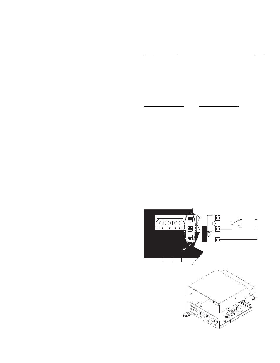
8.2 Custom Fuse Configuration: Push-Button 6
Functionality
Outlet #J13 does not function as an output terminal and is not used in the
default configuration. By changing the position of fuse #9 this terminal can
be configured to control an auxiliary circuit. This auxiliary circuit can not
exceed 20 amps.
Moving Fuse #9 from its default position (F9) to its optional position (F9A)
allows push-button 6 to control an auxiliary circuit. Connect Power In from
the AUX circuit to Outlet J13 and Load Out to Outlet J14 or J15. Push-but-
ton 6 will now open and close this circuit.
PC Board Power Fuse:
Remove the 4 screws holding
the cover on, remove the
cover and replace the
fuse. The internal fuse
should be replaced with
a 5 AMP fuse.
PCCS9R REAR VIEW
AUX CIRCUIT
POWER IN
+V BAT
FROM J9
Normally
Closed
O U T L E T S
J15
J15
J14
J14
J13
J13
F9
F9A
Normally
Open
FUSE
HERE
OR
HERE