Specifications, Mounting, Wiring the pccs9np – Whelen PCCS9NP User Manual
Page 3: Pin connector (power wires), Important: replacing a pccs9n
Page 3
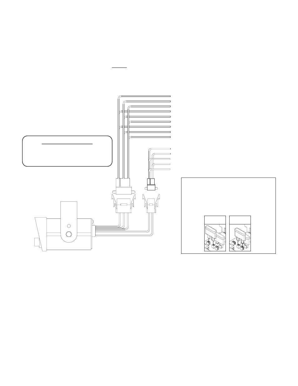
POS 1 (GRN)
POS 2 (BRN)
POS 3 (VIO)
POS 4 (BLU)
POS 5 (GRY)
POS 6 (WHT)
POS 7 (YEL)
POS 8 (ORN)
POS 9 (WHT/BLK)
- Slide Switch Output 1
- See Note
- SW9 (Momentary) Output
- Slide Switch Output 3
- Slide Switch Output 2
- SW5 Output
- SW6 Output
- SW7 Output
- SW4 Output
AMP 6
POSITION
SOCKET
CONNECTOR
AMP 9
POSITION
SOCKET
CONNECTOR
IMPORTANT! The push-button and slide switch control wires are designed to activate relays
with a coil rating no greater than 250 ma. Do not connect them to any circuit rated higher.
- SW8 Output
- See Note
- To +12VDC (Backlighting)
- To Chassis Ground
- To Aux Siren (optional)
POS 5 (WHT/RED)
POS 3 (WHT/GRN)
POS 1 (RED)
POS 2 (BLACK)
POS 4 (BLK/WHT)
NOTE: When the slide switch control fuse is in its default
position, the RED wire will be used to provide
power for both the slide switch and push-button
switches. The BROWN wire is not used in this situation.
When the slide switch control fuse is in its
optional position,
NOTE:
the BROWN wire will provide power
for the slide switch and the RED wire will provide power
for the push-buttons.
Fuse Pos.1
(default)
Fuse Pos.2
(If inter-connect
cable is used)
SPECIFICATIONS
Voltage:
Output Current (Max.):
12.8VDC ± 20%
250 mA per Wire
Mounting:
An aftermarket center console is recommended for the mounting location. If console mounting is not possible, the unit includes a bail
strap mounting kit for over or under dash mounting. Refer to the Air Bag Deployment Warning on the front sheet of this manual for
important mounting guidelines!
Wiring the PCCS9NP:
WARNING! All customer supplied wires that connect to the positive terminal of the battery must be sized to supply at least
125% of the maximum operating current and FUSED at the battery to carry that load. DO NOT USE CIRCUIT BREAKERS WITH
THIS PRODUCT (see customer wire chart).
6-Pin Connector (Power Wires)
1.
Connect the 9-pin power connector (see wiring diagram)
into the 9-pin pigtail connector provided.
2.
Extend the RED wire to a +12VDC accessory circuit. Install
a 5 amp fuse block (customer supplied) onto the end of the
wire and complete the connection to the selected power
circuit (remove the fuse before connecting any wires).
IMPORTANT: There must not be more than 2 feet of wire
between the fuse block and the battery. The wire between
the fuse and the battery is “unprotected.” Do not allow this
wire to come in contact with any other wires.
3.
Connect the BLACK wire to chassis ground.
4.
Extend the WHITE/RED wire to a +12VDC source that is
activated with the vehicle ignition switch.
5.
Extend the WHITE/GREEN wire to an auxiliary siren
control line (optional).
6.
The BLACK/WHITE wire is the SW8 output wire. Connect
to the desired control wire.
IMPORTANT: Replacing a PCCS9N
If the PCCS9NP is replacing a model PCCS9N controller, it will
be necessary to replace the existing 4-pin cable previously
used on the vehicle in question.
Additionally, the following changes must be made to the
PCCS9NP itself. First, the rear, outer fuse on the PCCS9NP
circuit board must be moved from its default position into fuse
position 2 (see illustration above). Note that the PCCS9NP
cover must be removed to access this fuse. Finally, the dip
switch settings for banks 1, 2 & 3 must be set as shown on the
following page.