Dip switch chart / 4-position / bank 4, Pin connector (output control wires), Configuring slide switch control – Whelen PCCS9NP User Manual
Page 4: Page 4, Default (factory) setting shown
Page 4
off off off
SWITCH 9 CAN TO OPERATE IN 4 DIFFERENT MODES,
DEFINED BY THE 4 POSITION DIP SWITCH
:
-
(Bank 4)
PANEL SWITCH 9
OPERATING MODE:
MOMENTARY
1 2 3 4
MODE 1 (DEFAULT)
PANEL SWITCH 9
OPERATING MODE:
8 SECOND ON TIMER
off off
on
1 2 3 4
MODE 2
PANEL SWITCH 9
OPERATING MODE:
LATCH ON
LATCH OFF
off off
on
on
on
on
on
1 2 3 4
MODE 3
PANEL SWITCH 9
OPERATING MODE:
FLASHER
(400MS ON & OFF)
off
off
on
1 2 3 4
MODE 4
ON
OFF
Down
(OFF)
Down
(OFF)
Down
(OFF)
Down
(ON)
DIP SWITCH CHART / 4-POSITION / BANK 4
Default (factory) setting shown.
Switch 9
(momentary)
1
ON
OFF
2
3
4
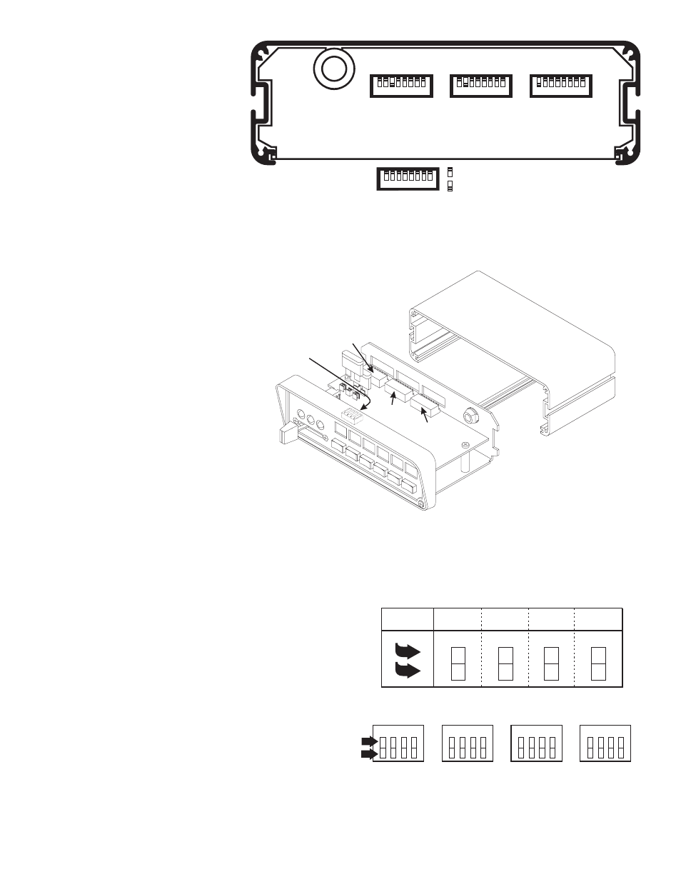
Custom Dip Switch Configuration (Dip Switch Bank 4):
Push-button 9 (momentary switch) can function in 4 different modes, defined by the 4-position dip switch bank 4. This bank is located on
top of the circuit board and is only accessible with the cover removed from the PCCS9NP.
Mode 1 - (default) - In this configuration, the output is activated for as
long as push-button 9 is depressed.
Mode 2 - In this configuration, when push-button 9 is pressed, the
output is activated for a period of 8 seconds.
Mode 3 - In this configuration, when push-button 9 is pressed, the
output is activated. When pressed again, the output is deactivated.
Mode 4 - In this configuration, when push-button 9 is pressed, the
output is activated for a period of 400 ms. After 400 ms, the output is
deactivated for 400 ms. This cycle will continue until push-button 9 is
pressed again.
Note - Dip Switch 1 is used to enable/disable the Aux Siren
(WHT/GRN) wire. In the default position (ON), this wire is
enabled. Moving Dip Switch 1 to the OFF position will disable
this wire. This switch should be left in the default position. If this
wire is not used, move Dip Switch 1 to the OFF position.
Dip Switch
Bank 1
Dip Switch
Bank 4
Dip Switch
Bank 2
Dip Switch
Bank 3
9-Pin Connector (Output Control
Wires):
Using the information shown in the
illustration on page 3, connect the
appropriate output wire to the desired input
control wire.
Configuring Slide Switch Control:
The slide switch has four positions: 0 (off),
1, 2 & 3. When in position 0 (furthest to the
left) the slide switch has not activated any
outputs. In position 1, 2 or 3 the slide
switch can activate any combination of
outputs 1 through 8. Each active slide
switch position uses a bank of dip switches
to determine which outputs are to be active
while the slide switch is in that position;
position 1 uses dip switch bank 1, position
2 uses dip switch bank 2 and position 3
uses dip switch bank 3.
Each dip switch bank is comprised of 8
switches, each representing a
corresponding output (switch 1 for output
1, switch 2 for output 2, etc.). If, for
example, switches 1, 3, 4 & 6 on dip switch
bank 1 are in the ON position, outputs 1, 3,
4 & 6 will be active when the slide switch is
moved to position 1.
Slide switch configuration is as simple as
deciding which outputs are to be active in a
given position and then moving the
corresponding dip switch on the
appropriate dip switch bank to the ON
position.
1 - Slide Switch Output 1 (GRN)
2 - Slide Switch Output 2 (GRY)
3 - Slide Switch Output 3 (BLU)
4 - Switch 4 Output (WHT/BLK)
5 - Switch 5 Output (WHT)
6 - Switch 6 Output (YEL)
7 - Switch 7 Output (ORN)
8 - Switch 8 Output (BLK/WHT)
8
7
6
5
4
3
2
1
Dip Switch
Bank 1
Dip Switch
Bank 2
Dip Switch
Bank 3
8
7
6
5
4
3
2
1
8
7
6
5
4
3
2
1
8
7
6
5
4
3
2
1
= OFF
= ON