Wiring, Power & ground wires: red: power / black: ground, Speaker wires: orange, yellow & brown – Whelen 295SLSA1 User Manual
Page 3: Horn relay wires: white & grey, Radio rebroadcast (optional): 2 blue wires, Input connectors
Page 3
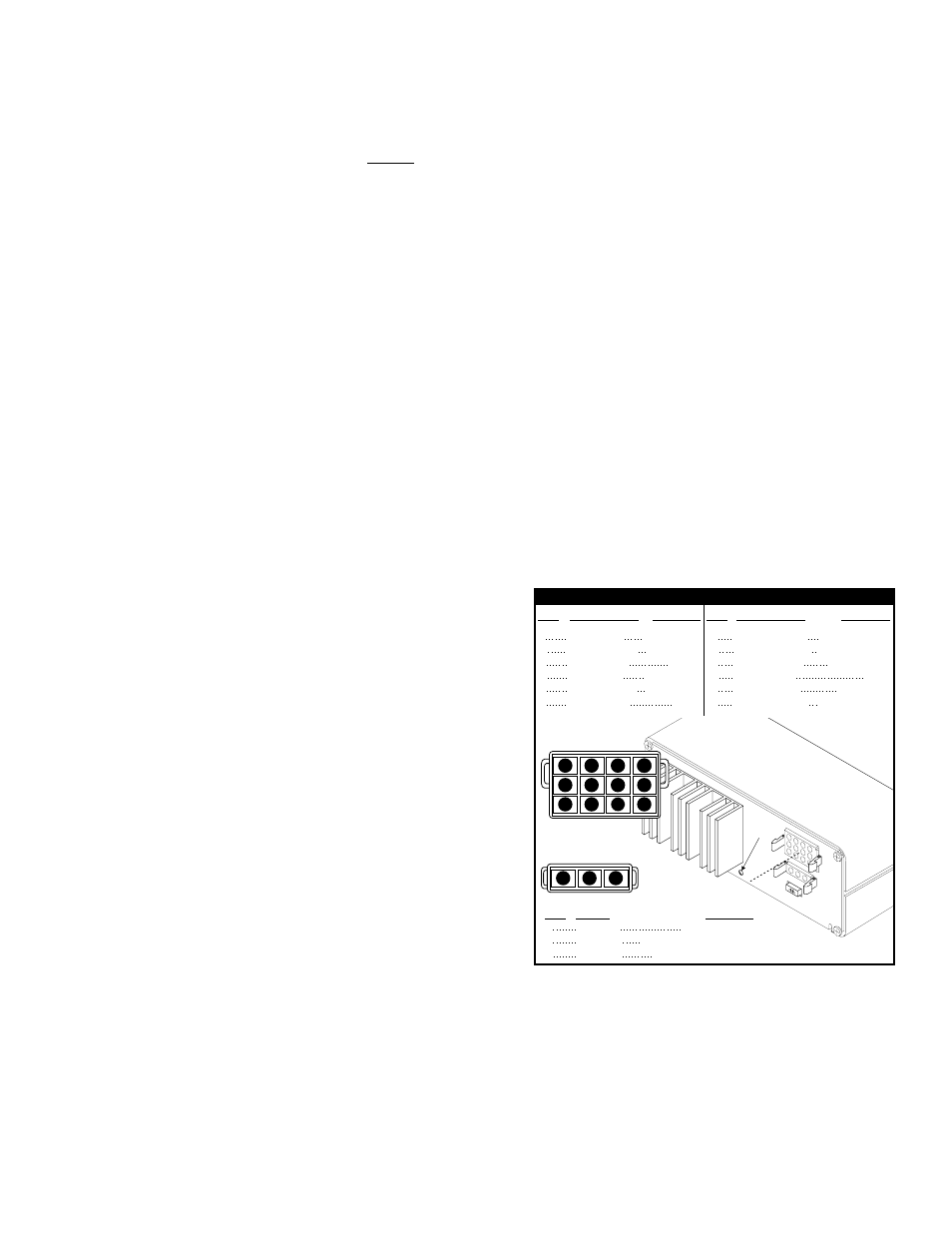
COLOR / GAGE
COLOR
PIN#
PIN#
FUNCTION
FUNCTION
RED 14GA
/
BLACK / 14GA
BLUE / 18GA
RED / 14GA
BLACK / 14GA
BLUE / 18GA
WHT/YEL
WHT/ORG
WHT/GRN
1
2
3
4
5
6
1
2
3
( )
(-) GROUND
RADIO
(+) BATTERY
(-) GROUND
RADIO
+ BATTERY
BACKLIGHTING
“SIREN IN USE” OUTPUT
SIREN INTERRUPTION
BROWN / 16GA
ORANGE / 16GA
VIOLET / 18GA
GRAY / 18GA
WHITE / 18GA
YELLOW / 16GA
7
8
9
10
11
12
SPEAKER COM
SPEAKER #2 (+)
AUX. ENABLE
HORN
HORN RING
SPEAKER #1 (+)
COLOR / GAGE
PIN#
FUNCTION
INPUT CONNECTORS
3-POS. CONNECTOR
(REAR VIEW)
Scan-Lock
Switch
1
2
3
INPUT CONNECTOR
(REAR VIEW)
3
2
1
6
5
4
9
8
7
11
10
12
Wiring:
Power & Ground Wires: RED: Power / BLACK: Ground
WARNING!
All customer supplied wires that connect to the positive terminal of the battery must be sized to supply at least
125% of the maximum operating current and FUSED at the battery to carry that load. DO NOT USE CIRCUIT BREAKERS WITH
THIS PRODUCT!
1.
Splice the 2 RED (Power) wires together, then extend this single RED wire toward the vehicle battery. Splice the 2 BLACK
(Ground) wires together and extend this single BLACK wire toward the vehicle battery. To pass the RED and BLACK wires
through, you may have to drill a hole in the firewall. Be sure there are no components that could be damaged. Insert a grommet in
the hole to protect the wires.
2.
Route the RED and BLACK wires along the factory harness towards the battery and install a fuse block (user supplied) on the end
of the RED wire (refer to the wiring schematic on page 4 for your model’s fuse value). NOTE: Remove the fuse from the fuse block
before connecting any wires to the battery.
3.
Connect the fuse block wire to the POSITIVE (+) terminal on the battery. There must not be more than 2 feet of wire between fuse
block and battery. The wire between the fuse and the battery is “unprotected,” don’t allow it to contact with any wires.
4.
Connect the BLACK wire to the factory chassis ground.
Speaker Wires: ORANGE, YELLOW & BROWN
1.
Route the ORANGE, YELLOW and BROWN wires toward the vehicle siren speakers, along the factory wire harness and through
the firewall at the same point as the RED and BLACK wires.
2.
Connect the YELLOW and ORANGE wires to the POSITIVE connection on speakers #1 & 2 (respectively).
3.
Connect the BROWN wire to the NEGATIVE connection on speakers #1 & 2.
Horn Relay Wires: WHITE & GREY
1.
Route the WHITE and GREY wires along the factory wire harness and through the firewall at the same point as the RED and
BLACK wires.
2.
Route the WHITE and GREY wires to your vehicle’s horn relay. If
possible, follow the factory wire harness to this relay.
3.
Locate the wire that connects the vehicle horn to the horn relay and
cut it.
4.
Connect the WHITE wire to the wire coming from the horn relay.
5.
Connect the GREY wire to the wire coming from the horn.
Radio Rebroadcast (optional): 2 BLUE wires
The two remaining BLUE wires are used to connect your two-way
radio’s external speaker for radio rebroadcast (an optional connection).
NOTE: If your remote speaker is amplified (has a power amp circuit in
the speaker), radio rebroadcast will not work and should not be enabled.
1.
Locate the two wires that connect the external speaker to the two-
way radio, cut one of them and splice one of the BLUE wires into
this circuit.
2.
Now cut the remaining speaker wire and splice the remaining BLUE
wire into this circuit.