Connecting to a remote control- head: (optional), Operating the controls, 295sls*1 sir e n – Whelen 295SLSA1 User Manual
Page 4: Wiring diagram, Power switch, Horn button, Rotary switch, Man button, Pa volume (mic), Page 4
Page 4
(+)
Battery
(-)
20 AMP FUSE (12V)
10 AMP FUSE (24V)
12-POS.
IINPUT
CONNECT
OR
3-POS.
IINPUT
CONNECT
OR
CHASSIS
GROUND
TO
2-W
AY
RADIO
SPEAKER
AUXILIARY
ENABLE
CONNECTION
(OPTIONAL)
BLUE
BLUE
BLACK
BLACK
WHT/GRN
Siren Interruption
Negative (-) Activation
100W
SPEAKER
#2
BROWN
WHITE
GREY
YELLOW
RED
WHT/ORG
To “Siren In Use” Icon
Input on Video Camera
RED
WHT/YEL
To Dashboard
Lighting Control
Voltage
3
6
9
5
2
3
7
11
10
12
4
2
1
1
VEHICLE
HORN
CUT
W
IRE
HERE
HORN
RELAY
+12V
TO
HORN
BUTT
ON
295SLS*1
Sir
e
n
100W
SPEAKER
#1
ORANGE
8
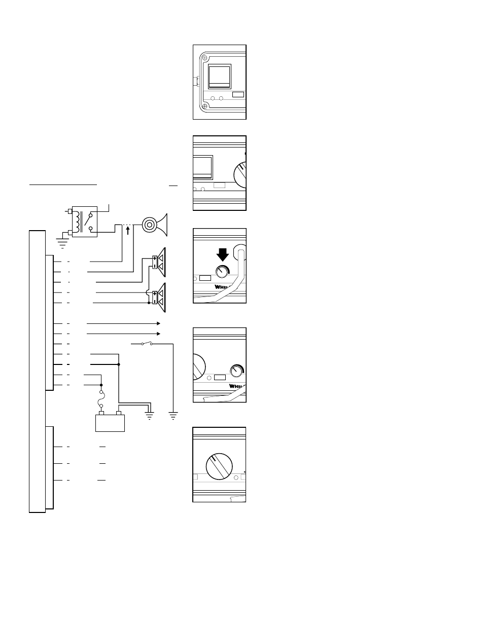
WIRING DIAGRAM
NOTE:
Do
use circuit breakers with this product!
All Fuses & Fuse Blocks are to
be supplied by the Customer.
NOT
VIOLET
(TO PCDS-9 or EQUIV.)
RAD
F
T3
HORN
MIC VOL.
T1
T2
Connecting to a Remote Control-
Head: (Optional)
This unit may be connected to an existing
control head, such as the Whelen PCCS9NP
or equivalent. This is an optional connection
that enables the WAIL tone to be activated
through the use of a PCCS9NP button or
switch. If this connection is not chosen, cut
the VIOLET wire and cap it to prevent
accidental grounding of the wire.
OPERATING THE CONTROLS:
Power Switch
This switch has two positions: Down (Off) and Up (On). When
this switch is Off, the unit will not function. When the switch is
On, the siren is functional and may be activated at the
operator’s discretion. This switch also activates control head
backlighting. NOTE: If the unit is connected to the vehicle’s
horn ring circuit, the vehicle horn is disabled when the power
switch is in the ON position.
M A N
RAD
MAN
SPEAKERS
POWER
1
2
Horn Button
Holding the HORN button on generates a AIRHORN tone
when the siren is powered up.
N
RAD
RAD
MAN 2
MAN 1
HF
T3
H
T1
T2
Rotary Switch
The Rotary Knob controls the siren functions. There are 7
positions that may be selected. Each position and its function
is outlined under “Rotary Switch Operations.”
M A N
RAD
MAN 2
MAN 1
PEAKERS
POWER
1
2
MAN Button
The Manual button generates a variety of tones, depending
on what position the rotary knob is in. For further explanation
of this button’s function, refer to “Rotary Switch Operations.”
®
AD
T3
HORN
MIC VOL.
T2
PA Volume (MIC)
With the vehicle in an enclosed area, turn the siren on and
speak into the microphone. While speaking, turn knob
clockwise to increase the volume. Continue to increase the
PA volume until audio feedback occurs. Turn counter-
clockwise to eliminate feedback.