Mounting, Wiring the 295hfs_5, Power wires – Whelen 295HFSA5 User Manual
Page 3: Speaker wires / yellow, orange & brown wires, Slide switch control wires / green, grey & blue, Horn relay wires / white & grey wires, Radio rebroadcast / blue wires (optional), Siren shut-down / violet wire (optional), Backlighting
Page 3
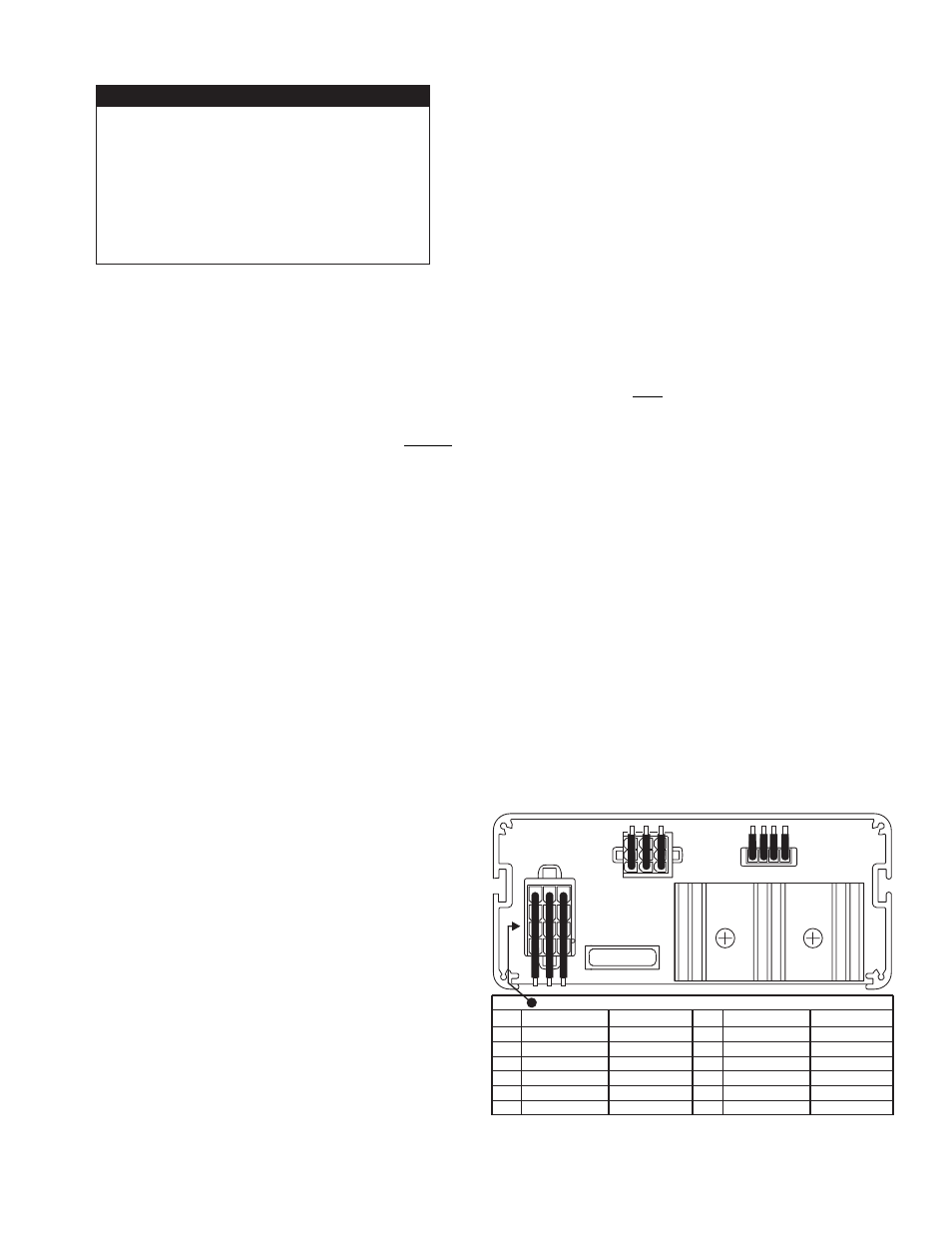
REAR VIEW
1
20 AMP FUSE
PIN #
1
2
3
4
5
6
COLOR & GAGE
RED 14GA
BLACK 14GA
BLUE 18GA
RED 14GA
BLACK 14GA
BLUE 18GA
FUNCTION
+ BATTERY
GROUND
RADIO
+ BATTERY
GROUND
RADIO
PIN #
7
8
9
10
11
12
COLOR & GAGE
BROWN 16GA
ORANGE 16GA
VIOLET 18GA
GRAY 18GA
WHITE 18GA
YELLOW 16GA
FUNCTION
SPEAKER COM
+SPEAKER #2
REMOTE ACT.
HORN
HORN/RING
+SPEAKER #1
12 POSITION SIREN INPUT CONNECTOR
P1
P4
P2
Mounting:
An aftermarket center console is recommended for the mounting
location. If console mounting is not possible, the unit includes a bail
strap mounting kit for over or under dash mounting.
Wiring the 295HFS_5
(refer to wiring diagram on pg. 6):
WARNING: All customer supplied wires that connect to the
positive terminal of the battery must be sized to supply at
least 125% of the maximum operating current and FUSED at
the battery to carry that load. DO NOT USE CIRCUIT
BREAKERS WITH THIS PRODUCT! (see customer wire chart)
Power Wires
1.
Insert the Siren Input Connector (P4) into its port.
2.
Splice the 2 RED wires together, then extend this single RED
wire to the battery. Install a 20 amp fuse block (customer
supplied) to the end of the wire and connect it to the POSITIVE
(+) terminal on the battery (remove the fuse before connecting
any wires to the battery).
IMPORTANT: There must not be more than 2 feet of wire between the fuse
block and the battery. The wire between the fuse and the battery is
“unprotected.” Do not allow this wire to come in contact with other wires.
3.
Splice the 2 BLACK wires together and connect them to the
negative terminal of the battery.
4.
Run the RED wire from Output P1 to the battery and connect it
to a 3 Amp fuse block, (customer supplied) then to the positive
terminal of the battery.
Speaker Wires / Yellow, Orange & Brown Wires
This section outlines a two-speaker installation. If using one
speaker, cut and cap the ORANGE wire, and skip steps 3 & 4.
1.
Run the YELLOW, ORANGE and BROWN wires to the vehicle
siren speakers.
2.
SPEAKER 1 -YELLOW to POSITIVE speaker connection and
BROWN to the NEGATIVE speaker connection.
3.
SPEAKER 2 - ORANGE to POSITIVE speaker connection.
4.
Splice a wire from the NEGATIVE connection on SPEAKER 1
to the NEGATIVE connection on SPEAKER 2.
Slide Switch Control Wires / Green, Grey & Blue
NOTE: The push-button and slide switch control wires are
designed to activate relays with a coil rating nogreater than 250
ma. Do not connect them to any circuit rated higher.
1.
Route and connect the GREEN wire to the desired lightbar
function control wire(s).
2.
Route and connect the GREY wire to the desired lightbar
function control wire(s).
3.
Route and connect the BLUE wire to the desired lightbar
function control wire(s).
Horn Relay Wires / White & Grey Wires
1.
Run the WHITE and GREY wires to the vehicle’s horn relay. If
possible, follow the factory wire harness.
2.
Cut the wire that connects the vehicle horn to the horn relay.
3.
Connect WHITE wire to wire coming from horn relay.
4.
Connect GREY wire to wire coming from horn.
Radio Rebroadcast / Blue Wires (Optional)
Radio rebroadcast will NOT work with amplified speakers. If your
remote speaker contains a power amp in the speaker, do not
enable the radio re-roadcast feature.
1.
Locate the two wires that connect the external speaker to the
vehicle’s two-way radio.
2.
Cut one of these wires and splice one of the BLUE wires into
this circuit.
3.
Cut the remaining speaker wire and splice the remaining
BLUE wire into this circuit.
Siren Shut-Down / Violet Wire (Optional)
The 295HFSA5 can be configured to cease all automatic siren
tones whenever the VIOLET wire from P4 is grounded through a
switch. If this is not desired, cut and cap the VIOLET wire.
Backlighting
When the power switch is on, the HFSA5’s backlighting is on.
When the power switch is off, backlighting can be turned on by
connecting the WHITE / RED wire from P2 to a +12VDC source
that is activated with the vehicle’s ignition switch.
READ BEFORE INSTALLING!!!
Do not install this product or route any wires in the deployment
area of your air bag. Equipment mounted or located in
the air bag deployment area will damage or reduce the
effectiveness of the air bag or become a projectile that could
cause serious personal injury or death. Refer to your vehicle
owner's manual for the air bag deployment area.
The User/Installer assumes full responsibility to determine the
proper mounting location, based on providing ultimate safety
to all passengers inside the vehicle. Whelen Engineering Co.
assumes no liability or responsibility for determining individual
applications or exact installation location criteria.