Configuring the slide switch functions – Whelen 295HFSA5 User Manual
Page 4
Page 4
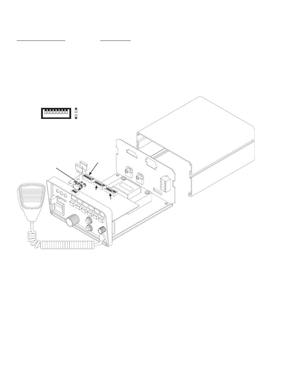
Configuring the Slide Switch Functions:
In the default dip switch setting, the P1 outputs are:
Slide Switch Positions:
Push-Buttons:
0 = Terminals OFF
4 = White / Black
1 = Green
5 = White
2 = Green / Grey
6 = Yellow
3 = Green / Grey / Blue
7 = Orange
8 = Black / White
9 = Violet
Changing Default Slide Switch Control:
Configuring Slide Switch Control:
The slide switch has four positions: 0 (off), 1, 2 & 3. When in position 0 (furthest to the left) the slide switch has not activated
any outputs. In position 1, 2 or 3 the slide switch can activate any combination of outputs 1 through 8. Each active slide
switch position uses a bank of dip switches to determine which outputs are to be active while the slide switch is in that
position; position 1 uses dip switch bank 1, position 2 uses dip switch bank 2, and position 3 uses dip switch bank 3.
Each dip switch bank is comprised of 8 switches, each representing a corresponding output (switch 1 for output 1, switch 2
for output 2, etc.). If, for example, switches 1, 3, 4 & 6 on dip switch bank 1 are in the ON position, outputs 1, 3, 4 & 6 will be
active when the slide switch is moved to position 1.
Slide switch configuration is as simple as deciding which outputs are to be active in a given position and then moving the
corresponding dip switch on the appropriate dip switch bank to the ON position.
1 - Slide Switch Output 1 (GRN)
2 - Slide Switch Output 2 (GRY)
3 - Slide Switch Output 3 (BLU)
4 - Switch 4 Output (WHT/BLK)
5 - Switch 5 Output (WHT)
6 - Switch 6 Output (YEL)
7 - Switch 7 Output (ORN)
8 - Switch 8 Output (BLK/WHT)
8
7
6
5
4
3
2
1
= OFF
= ON
Dip Switch
Bank 1
Dip Switch
Bank 4
Dip Switch
Bank 2
Dip Switch
Bank 3