0 front panel, Fig. 3, Page 3 – Whelen 295SLSA6 User Manual
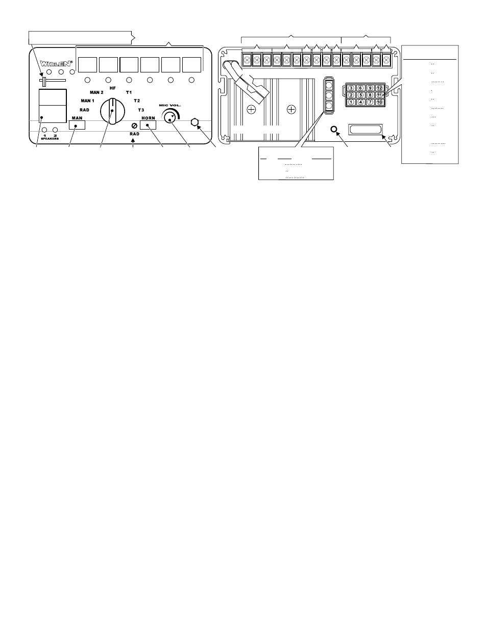
Page 3: 2 3-position input connector, 3 main power wires - 10 awg, 1 power switch, 2 rotary switch, 3 volume knob, 4 radio repeat volume, 5 man button
Page 3
Power
Switch
Manual
Programmable Power
Distribution Control
Rotary
Switch
Microphone
Volume
Mic.
Input
F u s e
Holder
Radio Repeat
Adjusts volume
Air
Horn
Slide Switches
Push Buttons
20 Amp Fuse
13
14
1
2
3
4
5
6
7
8
9
10
11
12
15
Scan Lock™
Button:
-
Momentary switch.
Use a non-conductive
item to push in.
Controls
Terminal
7
Controls
Terminal
8
Controls
Terminal
9
Controls
Terminals
10-11-12
Controls
Terminal
13-14-15
1
2
3
1
2
3
4
5
6
Rear View of Siren
Controls
Terminal
6
3 Position Connector
COLOR
PIN
FUNCTION
WHT/YEL
WHT/ORG
WHT/GRN
1
2
3
BACKLIGHTING
SIREN IN USE OUTPUT
AUX. ENABLE
SIREN
INTERRUPT
1
2
3
Siren Input Connector
PIN / WIRE / GAGE / FUNCTION
RED 14GA
/
BLK / 14GA
BLU / 18GA
RED / 14GA
BLK / 14GA
BLU / 18GA
BRN / 16GA
ORG / 16GA
VIO / 18GA
GRY / 18GA
WHT / 18GA
YEL / 16GA
YEL / 16GA
1
2
3
4
5
6
7
8
9
10
11
12
( )
(-) GROUND
RADIO
(+) BATTERY
(-) GROUND
RADIO
SPKR COM
(+) SPKR #2
HORN
HORN/RING
(+) Speaker # 1
+ BATTERY
Fig. 3
3 Pos. Slide Switch: 0 = Off 1 Controls Terminal 1
2 Controls Terminal 2 3 Controls Terminals 3, 4 & 5
2.2 3-Position Input Connector:
WHITE/GREEN - Aux Enable:
This wire is activated by switching it to ground (see section 4 for operation).
WHITE/ORANGE - Siren in Use:
Extend the WHITE/ORANGE to the icon input of a video camera. This wire is active
positive whenever a siren tone is being produced (200ma max).
WHITE/YELLOW - Backlighting:
Extend the WHITE/YELLOW to the parking light positive voltage. This input is used
to drive the backlighting of the siren when the power is off.
2.3 Main Power wires - 10 AWG:
RED - Power / +12VDC:
1.
Extend the two 10 AWG RED wires along the vehicle factory wire harness
towards the battery. Install a 60 AMP fuse block (user supplied) on the ends of
each of these wires (see table 1 for correct wire size).
WARNING!
Remove the fuse from the fuse block before connecting any
wires to the battery.
2.
Connect each fuse block wire to the positive (+) terminal of the battery. There
must not be more than 2 feet of wire between the fuse blocks and the battery.
The wire between the fuse and battery is “unprotected,” do not allow it to chafe
and short to ground.
3.0 Front Panel:
3.1 Power Switch
This switch has two positions; Up (On) and Down (Off). When this switch is off, siren
functions are disabled, however the power distribution switching can be programmed
to operate independently of the power switch (default) or activate only when the
power switch is on (see section 6.6).
WARNING!If the 295SLS is connected to the vehicle’s horn ring circuit, the
vehicle horn is disabled when the power switch is ON.
3.2 Rotary Switch
The Rotary Knob controls the siren functions of the 295SLS. There are 7 positions
that may be selected (see Section 4.0.).
3.3 Volume Knob
The Volume Knob controls the volume of Public Address function. Volume is
increased by rotating the knob in a clockwise direction. Rotating the Volume Knob in
a counter-clockwise direction decreases the volume produced by these features. The
volume knob has no effect on siren tones or radio repeat volume.
3.4 Radio Repeat Volume
Before using the 295SLS, the Radio Repeat output volume must be adjusted to satis-
factory operating levels. To adjust this level, a small, flat-blade screwdriver is
needed. Locate the Radio Repeat adjustment port (potentiometer) to the right of the
Rotary Knob on the face of the control head. Set the volume level of the vehicle’s
two-way radio to its normal operating volume. Turn the Rotary Knob on the control
head to RAD to activate Radio Repeat. Insert the screwdriver in the Radio Repeat
adjustment port and turn in a clockwise direction to increase the sound level.
3.5 MAN Button
The Manual button generates a variety of tones, depending on what position the
rotary knob is in (see Section 4.0.).
3.6 SI TEST® & Diagnostic Indicators
SI TEST is a diagnostic feature of the 295SLS and allows the operator to confirm the
proper operation of the siren speakers connected to the unit without activating an
audible siren tone. To initiate SI TEST cycle, set the rotary knob to the RAD position.
Now press and release the MAN button. As the siren is tested, its diagnostic indicator
will turn on steady for about 1.5 seconds if no problems are detected. If the indicator
flashes, or does not light at all, a problem with either the siren, speakers, or wiring
has been detected. Check the wire connections of the failed speaker and repeat the
SI TEST. If the speaker fails to test again, have the siren itself inspected by a quali-
fied technician. NOTE: Installed speakers are tested by generating an ultra-high fre-
quency tone through each speaker. Although these tones are inaudible to humans,
be sure no one is within 5 feet of the speakers when SI TEST is running.
Diagnostic Indicators:
While this siren is under normal use the diagnostic indicators are used to indicate
fault conditions with your siren system. The following table lists the type of fault and
the indicators response. If the indicator is on steady while a tone is in use, this
implies that there is no fault with the associated speaker output.
Fault Condition Diagnostic Indicators Response
Under Voltage Speaker LED #2 will be in a DoubleFlash mode (2 quick flashes
followed by a longer pause) and siren tones won’t operate.
Over Voltage Speaker LED #1 will be in a DoubleFlash mode (2 quick flashes
followed by a longer pause) and siren tones will not operate.
Speaker #1
Speaker LED # 1 will be in a SingleFlash mode (the LED will be on
Short Circuit and off an equal amount of time) and siren tones won’t operate.
Speaker #2
Speaker LED #2 will be in a SingleFlash mode (the LED will be on
Short Circuit and off an equal amount of time) and siren tones won’t operate.
Speaker #1
Speaker LED #1 will be off (having a single speaker system will
Open Circuit
always cause this condition for the speaker output not in use) all
tones will continue to operate.
Speaker #2
Speaker LED #2 will be off (having a single speaker system will
Open Circuit always cause this condition for the speaker output not in use) all
tones will continue to operate.
3.7 Horn Button
Power up the siren and hold the HORN button on to generate an AIRHORN tone.
3.8 Programmable Power Switches:
The power distribution switches include the slide switch and the six momentary
switches. The slide switch having one off position and three active positions com-
bined with the six momentary switches makes a total of nine switch positions. For
each of the nine switches there are corresponding outputs on the terminal block in
the back of the unit. Each of the nine switches will always activate it’s own corre-
sponding output, but can be programmed to activate any of the other outputs and/or
activate the siren as well (see Section 6.0).
3.9 Microphone:
Whenever the siren is on, activating the microphone (pressing the switch on the side
of the mic.) will shut down any other siren functions and enable public address
operation regardless of the rotary switch position or any other switch or input.