3 siren tone programing procedures – Whelen 295SLSA6 User Manual
Page 5
Page 5
WAIL
YELP
PIERCER™
Y-249
HI/LOW
SIMULATED MECHANICAL
TABLE 5
Tone List For Hands Free Operation:
PULSED AIRHORN
AIRHORN HI/LOW
ALTERNATE WAIL
ALT. YELP
WOOP
WARBLE
..
..
..
..
..
..
= Title 13 Compliant Tones
*
= Title 13 Compliant Tones
*
*
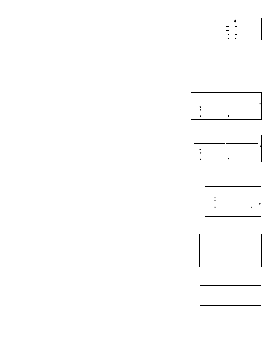
TABLE 4
Override Tone List For Rotar Switch Positions T1, T2 & T3
y
TONE OFF
WAIL
YELP
PIERCER™
Y-249
..
..
.
ALTERNATE YELP
WOOP
WARBLE
AIRHORN
LOW FREQ. HORN
..
..
.
HI/LOW
SIMULATED MECHANICAL
PULSED AIRHORN
AIRHORN HI/LOW
ALTERNATE WAIL
..
..
.
TONE OFF
AIRHORN
LOW FREQUENCY
AIRHORN
TABLE 7
Override Tone List For Rotary Switch Position RAD
and the HORN button:
..
.
TONE OFF
MANUAL SIMULATED MECHANICAL COAST-TO-STOP
MANUAL SIMULATED MECHANICAL STOP
MANUAL WAIL COAST-TO-STOP
MANUAL WAIL STOP
AIRHORN
LOW FREQ. AIRHORN
TABLE 6
Tone List For MAN1 & MAN2 Operation:
..
..
..
.
6.0 Programming the 295SLS*6:
WARNING: Never try to program the siren while it is wired to the vehicle. The
siren must be removed from the vehicle before programming. A low level audio
device is built into the siren so siren tones can be heard during programming.
6.1
Power Distribution Switch Output Programming:
The lighting control switches include the slide switch and the 6 momentary switches.
The slide switch has one off position and 3 active positions, combined with the 6 mo-
mentary switches makes a total of 9 active switches. For each of the 9 switches there
is 9 corresponding outputs on the terminal block. Each of the 9 switches will always
activate its own corresponding output, but can also be configured to activate any other
outputs and/or activate the siren.
To Configure a Switch's Outputs:
For programming, connect positive (+) battery and ground only.
1. Put the unit into "switch output" configuration mode.
•
Turn the POWER switch OFF.
•
Place the SLIDE SWITCH in the OFF position.
•
Place the ROTARY SWITCH into the HF position.
•
Hold the Scan-Lock™ switch in while turning power on.
To confirm entry into this configuration mode: Speaker #2 indicator light
will flash until a switch is selected to be configured.
2. Select a switch to be configured.
•
Press and continue to hold the switch to be configured.
•
Press and release the MAN switch.
•
Release the switch to be configured.
OR...
•
Place the slide switch in the position to be configured.
•
Press and release the MAN switch.
•
Leave the slide switch in the position to be configured.
The desired switch's indicator light will begin to flash, and any switch's
indicator light whose corresponding output is already in the selected switch's
configuration will turn on steady. Speaker# 1 indicator light will turn on steady
if auxiliary siren control is selected to be activated.
3. Add or Delete Outputs Activated by a Switch:
Press and release one of the six momentary switches to add or delete its
corresponding output. This switches indicator light will turn on steady when its
corresponding output is selected to be activated.
OR...
Press and release the HORN switch to cycle though the SLIDE SWITCH
corresponding outputs. Stop when indicator lights equal the desired output pattern.
OR...
Press and release the Scan-Lock switch enabling or disabling auxiliary siren
control by the selected switch. Speaker #1 indicator light will turn on steady when
auxiliary siren control is selected to be activated.
4. Store the Selected Switch's Output Pattern.
Press the microphones PUSH TO TALK switch. Speaker #2 indicator light will begin
to flash, all other indicator lights will turn off and the data will be stored.
To continue configuring other switches, place the SLIDE SWITCH in the off
position and start back at step 2. When programming is done, turn power off
and then on to activate the changes.
6.2 Power Distribution “Switch Type” Programming:
The 6 momentary lighting control switches located along the top right side of the siren
can be configured to operate as 1 of 4 types. The 4 types are: Push On Push Off,
Momentary, Flashing Output, and Timed Output (8 seconds).
To Configure a Switch Type, Follow the Steps Below:
1. Put the Unit into "Switch Type” Configuration Mode:
•
Turn the POWER switch off.
•
Place the SLIDE SWITCH in the off position.
•
Place the rotary switch to RAD.
•
Hold Scan-Lock switch in while turning the power switch on.
To confirm entry into this mode, speaker #1 indicator light will flash until a
switch is selected to be configured.
2. Select a Switch to be Configured:
•
Press and continue to hold the switch to be configured.
•
Press and release the MAN switch.
•
Release the switch to be configured.
The desired switch indicator light will turn on steady. Speaker indicator lights will
display a pattern corresponding to the type of switch that is already selected.
3.
Choose a Switch Type for the
Selected Switch:
•
Press and release the HORN switch to cycle
though the switch types (table 2).
•
Stop when indicator lights equal desired pattern.
4.
Store the Selected Switch's Output Pattern.
•
Press the microphones PUSH TO TALK switch.
•
The Speaker #1 indicator light will begin to flash, all other indicator lights will
turn off, and the data will be stored.
•
When done programming, turn power off and then on to activate the changes.
6.3 Siren Tone Programing Procedures
With Scan-Lock the tonal operation of the siren can be customized to fit your
needs. Scan-Lock is used to change the default siren tones as shown below.
To change the primary tone for rotary switch positions T1, T2, & T3:
Put the rotary switch in the
position that you wish to change.
Press and release the Scan-
Lock switch. Each time the
Scan-Lock switch is pressed and
released, the next available tone
will be broadcast. When the
desired tone is generated, it is
automatically saved for that rotary switch position.
To change the override tone for rotary switch positions T1, T2. & T3:
Put the rotary switch in the
position that you wish to
change. Press and hold the
MAN button on the front panel
on the siren. Press and release
the Scan-Lock switch. Each
time the Scan-Lock switch is
pressed and released, the next
available tone will be broadcast. When the desired tone is present, it will
automatically be saved as the override tone for that rotary switch position. Release
the MAN button.
To change one of the tones in the hands free cycle
(see Section 4.4):
Put the rotary switch in the HF position.
Using the MAN button on the front panel
on the siren, advance to the tone that you
wish to change. Press and release the
Scan-Lock switch. Each time the Scan-
Lock switch is pressed and released, the
next available tone will be broadcast.
When the desired tone is generated, it will
automatically be saved for that hands-free
cycle position.
To change the tone for rotary switch positions MAN1 or MAN2:
Put the rotary switch in the position
that you wish to change. Press and
hold the MAN button on the front panel
on the siren. Press and release the
Scan-Lock switch. Each time the
Scan-Lock switch is pressed and
released, the next available tone will
be broadcast. When the desired tone
is generated, it will automatically be
saved for that rotary switch position.
Release the MAN button.
To change the override tone for rotary switch position RAD:
Put the rotary switch in the RAD
position. Press and hold the MAN
button on the front panel on the siren.
Press and release the Scan-Lock
switch. Each time Scan-Lock is
pressed and released, the next
available tone will be broadcast. When the desired tone is generated, it will
automatically be saved for that rotary switch position. Release the MAN button.
To change the tone for the HORN button:
Put the rotary switch in the MAN2
position. Press and hold the horn button on the front panel of the siren. Press and
release the Scan-Lock switch. Each time the Scan-Lock switch is pressed and
released, the next available tone will be broadcast. When the desired tone is
generated, it is automatically saved for HORN button activation (Table 7).
Push On Push Off
Timed Output
Momentary
Flashing Output
Off
Off
On
On
1
Off
On
Off
On
2
Table 2
LED Speaker Indicator
TONE OFF
WAIL
YELP
PIERCER™
Y-249
HI/LOW
SIMULATED MECHANICAL
PULSED AIRHORN
AIRHORN HI/LOW
ALTERNATE WAIL
= Title 13 Compliant Tones
*
*
TABLE 3
y
Tone List For Rotar Switch Positions T1, T2 & T3
ALTERNATE YELP
WOOP
WARBLE
..
..
.
..
..
.
..
.