Hands-free siren (items 33 & 37) (optional), Pa volume adjustment, Radio repeat volume adjustment – Whelen HHS2200 User Manual
Page 5: Amp/relay module fuses, Isolated relay (outlet 9), Hand-held controller default push button operation
Page 5
F1
(POS.1)
Common (6-5 WHT)
Normally Closed
(6-3 WHT/BLU)
Normally Open
(6-4 WHT/BLK)
Fuse in
Dry-Contact
Position
Fuse in
15 Amp Outlet
Position
F1
(POS.2)
+12VDC
OUTLET
#1
OUTLET
#2
OUTLET
#3
OUTLET
#4
OUTLET
#5
OUTLET
#6
OUTLET
#7
OUTLET
#8
F3
F2
F1
F4 F5 F6 F7 F8
F9
F10
SIREN
-20-
-10-
-10-
-10-
-10-
-10-
-10-
-10-
-10-
-15-
-15-
Radio Repeat
Potentiometer
PA Volume
Potentiometer
Pos.1: ISOLATED RELAY
POSITION
Pos.2: 15A OUTLET
POSITION
F1
F2
F3
F4
F5
F6
F7
F8
F9
F10
-
-
-
-
-
-
-
-
-
-
see text
Outlet #1
#2
#3
#4
#5
#6
#7
#8
Siren
Outlet
Outlet
Outlet
Outlet
Outlet
Outlet
Outlet
Module Fuses
A
A -
B -
C -
1 -
2 -
3 -
4 -
5 -
6 -
7 -
8 -
9 -
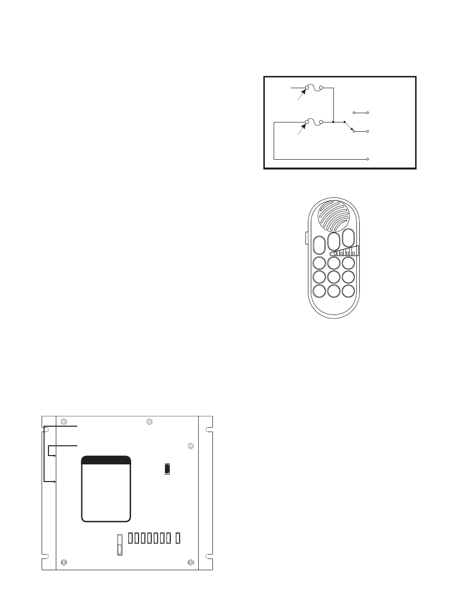
Note:
Keypad lighting
may be suspended
when the P-T-T
button is activated.
Outlet 1
Outlets 1 & 2
Outlets 1, 2 & 3*
H/F (Outlet 9)
MAN
Airhorn
Siren
Radio
Alley (Outlets 4 & 5)
Outlet 6
Outlet 7
Outlet 8
B C
1
4
7
2
5
8
3
6
9
LCPA Low Current Power Activation Inputs
(5-3 WHT/RED or 5-8 RED/WHT)
If desired, this system can be switched on (or activated) using Low
Current Power Activation (LCPA) inputs. This is accomplished by
connecting the appropriate LCPA input wire to the desired signal. If the
polarity of the signal to be used is Positive (+), use LCPA Input 5-3. If the
polarity of the signal is Negative (-), use LCPA Input 5-8.
Park-Kill (Item 5-5 WHT/GRN or 5-10 GRN/BLK)
This feature will automatically suspend an active siren tone when the
transmission is shifted into Park. If this feature is desired, the installer
must first determine if the signal wire from the transmission neutral safety
switch is switching the positive or negative side of the circuit. Use 5-5 if the
signal is switching Positive. Use 5-10 if the signal is switching Negative.
Using 18 to 22 gage wire, extend and connect the appropriate wire from
the amp/relay module to the vehicle’s transmission neutral safety switch
signal wire.
Hands-Free Siren (Items 33 & 37) (Optional)
Hands-Free connection allows siren tones to be initiated and controlled
using the vehicle horn ring button. Using a customer supplied relay
capable of handling the current of your vehicle horn, connect as shown on
page 7.
PA Volume Adjustment
Locate the PA adjustment pot (potentiometer) on the side of the amp/relay
module. Using a small, flat-blade screwdriver, set the potentiometer to its
middle position. With the system on, activate the PTT (Push To Talk)
feature on the optional microphone. Adjust the potentiometer until a
satisfactory PA volume level is achieved using a normal speaking voice.
Radio Repeat Volume Adjustment
To Adjust the Radio Repeat Levels: Before placing this unit into service,
the Radio Repeat output volume must be adjusted to satisfactory
operating levels. To adjust this level, a small, flat-blade screwdriver is
needed. Locate the Radio Repeat adjustment potentiometer on the side of
the amp/relay module. Set the volume of the vehicle’s two-way radio to it’s
normal operating level. Press the RAD button on the control head to
activate Radio Repeat. As incoming transmissions are received, adjust
the Radio Repeat potentiometer to set the desired level. Turn the
potentiometer clockwise to increase the level and counter-clockwise to
decrease the level.
Amp/Relay Module Fuses
For ease of access, all of the amp/relay module fuses are accessible from
outside the case.
Isolated Relay (Outlet 9)
The position of Fuse F1 determines the function of wires 6-3, 6-4 & 6-5.
When the fuse is in Position 1, these wires act as a Isolated 15 Amp
Relay. When the fuse is in Position 2, wires 6-3 and 6-4 act as Outlet #9.
Refer to the schematic shown for the electronic properties of this circuit.
Hand-Held Controller Default Push Button Operation
Button A - This button activates Outlet 1.
Button B - This button activates Outlets 1 & 2.
Button C - This button activates Outlets 1, 2 & 3. NOTE: If Dip Switch 3 is
in the ON position, this button will also turn the siren on.
Button 1 - This button puts the siren into Hands-Free mode. In this mode,
the WAIL tone is initiated by either pressing the Horn Ring or Button 2
(see Button 2 for details).
Button 1 also activates Outlet 9.
Button 2 - While Button 1 is active, pressing this button (or the horn
ring) will produce a WAIL tone. Subsequent presses of the horn ring or
button 2 will cycle the tone between WAIL and YELP. Two rapid presses
will stop the tone. While Button 1 is inactive, pressing Button 2 will
generate a tone that will ramp up to and sustain a specific pitch until this
button is released.
Button 3 - This button will broadcast the Airhorn tone until it is released.
This tone will over-ride all other siren tones.
Button 4 - This button activates the WAIL tone. A second press will stop
that tone. Pressing button 2 will change the tone to YELP.
Button 5 - This button will rebroadcast your radio output through the siren
speaker. This button is enabled by default.