Amp/relay module input/output identification – Whelen HHS2200 User Manual
Page 8
Page 8
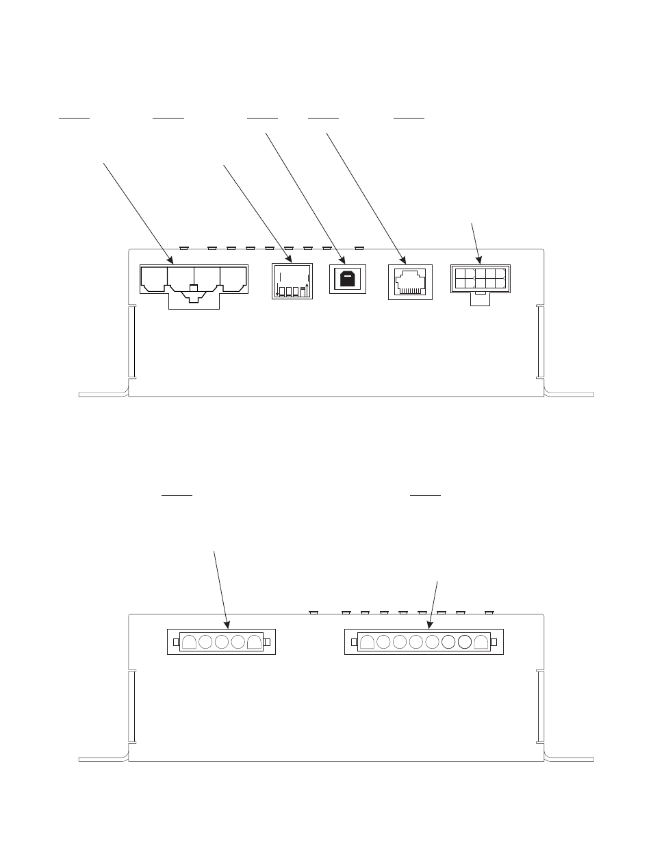
Amp Relay Module I/O
Wiring ID
Amp/Relay Module
Input/Output Identification
Item #5
5-1
Radio In
5-2
Backlight
5-3
Low Current System Switch (+ Activation)
5-4
Horn Ring (+ Activation)
5-5
Park Kill (+ Activation)
5-6
Radio In
5-7
Icon Driver
5-8
Low Current System Switch (- Activation)
5-9
Horn Ring (- Activation)
5-10 Park-Kill (- Activation)
Item #7
7-1
Outlet #1
7-2
7-3
7-4
7-5
7-6
7-7
7-8
Outlet #2
Outlet #3
Outlet #4
Outlet #5
Outlet #6
Outlet #7
Outlet #8
Item #6
6-1
Siren
6-2
Siren
-3
Isolated Relay (Normally Closed)
-4
-5
6
6
Isolated Relay (Normally Open)
6
Isolated Relay (Common)
Item #4
Controller Port
Item #3
USB Port
Item #2
2-1
Dip Switch #1
2-2
Dip Switch #2
2-3
Dip Switch #3
2-4
Dip Switch #4
Item #1
1-1
1-2
1-3
1-4
Relay (+)
Relay (+)
Siren (+)
Ground (-)
1
4
3
2
1
2 3 4 5
6 7 8 9 10
1
ON
OFF
2
3
4
1 2 3 4 5
1 2 3
5 6 7 8
4