Whelen RFNF85 User Manual
Page 3
Page 3
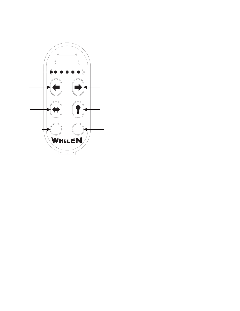
S/L
OFF
LED
Indicators
Left
Arrow
Right
Arrow
Split
Arrow
Scan-Lock™
Flash
Off
Button
Operation
As shown here, the controller is comprised of six (6) buttons
and 5 LED indicators
Arrow Buttons - There are three Arrow buttons; Left, Right
and Split. Pressing these buttons will initiate their designated
sequence. There are five (5) different sequence styles in
which these sequences are displayed. The selected
sequence style is applied to all three arrow buttons.
The sequence style selected will be used for all three buttons.
The 5 styles are as follows:
Solid Arrow (default)
Solid Half Arrow
Sequence to TripleFlash™
Sequence to Solid
Sequence On / Sequence Off
For information on changing styles, please refer to the “Scan-
Lock” section of this manual.
Flash Button - The Flash button will activate one of three (3)
available displays. They are as follows:
Flash Tips (default)
Flash Bar
Flash Tips and Bar
For information on changing displays, please refer to the
“Scan-Lock” section of this manual.
Scan-Lock - The Scan-Lock button is used to change the
styles used for the Arrow buttons and the display used by the
Flash button. This button operates as follows:
1.
Press and hold the desired Arrow (Left, Right, Split) or
Flash button.
2.
While holding the Arrow or Flash buttons, press and hold
the Scan-Lock (S/L) button for less than one (1) second
and release. This will advance the current style or
display to the next style or display.
3.
Release the Scan-Lock button and allow the selection to
run for a minimum of 5 seconds to designate it the
default style/display.
IMPORTANT! In areas where the type of pattern
displayed is mandated by State, County or Municipal
authorities, this function may be disabled. In these
regions, the Scan-Lock button will still be used for the
binding procedure.
Off - The Off button is used to turn off the Traffic Advisor™.
LED Indicators - There are five (5) LED Indicators located
on the face of the controller. These LEDs provide a brief
visual representation of the Sequence or Display selected.
These indicators also provide important information during
the Binding process. Refer to the “Binding Procedure”
section for more information.
Backlight - The controller features backlighting to aid
nighttime operation. Backlighting is activated whenever any
button is pressed and will remain on for approximately 3
seconds after the last button press.
Low Battery Indicator - When it is time to replace the
controller batteries, the OFF button will periodically flash red.
If this behavior is noticed, replace the batteries immediately.
Controller Mounting Clip - A mounting clip is included with
this controller. This provides a place for the operator to keep
the controller when it is not in use. When determining a
mounting location for this clip, it is important to select a
location that does not place either the clip or the clip/
controller where it could interfere with any existing
equipment.
IMPORTANT
AIR BAG
WARNING!
Do not install this
product in the air bag deployment zone of your vehicle.
Equipment mounted or located in air bag deployment
zones will damage or reduce the effectiveness of the air
bag, or become a projectile that could cause serious
personal injury or death. Refer to your vehicle owners
manual to learn the air bag deployment zones for the
vehicle. The User/Installer assumes full responsibility to
determine proper mounting location, based on providing
ultimate safety to all passengers inside the vehicle.