Installation, Bottom mount, Center mount: optional – Whelen G1PA User Manual
Page 2: Temporary mount (magnetic, suction cup, etc.), Top mount
Page 2
IMPORTANT! The lightbar should be located a minimum of
16" from any radio antennas!
Installation:
•
Since this installation will require drilling, it is absolutely
necessary to make sure that no other vehicle components will
be damaged in the process. Check both sides of the mounting
surface before starting and if damage is possible, select a
different mounting location.
•
Always deburr all holes and remove any metal filings from the
vehicle.
Bottom Mount
1.
Be sure the mounting area is relatively flat. Using the information in
figure 2 scribe the 4 mounting hole locations onto the mounting
surface.
2.
Mark off the wire access hole, located right behind the lightbar.
3.
Drill the mounting holes you marked off in step 1 with a 3/16” drill bit
and the wire access hole with a 3/8” drill bit.
4.
Install a 3/8” rubber grommet in the wire access hole and route the
wires through, then apply a silicone sealing compound around the
wires and grommet.
5.
Carefully position the lightbar over the mounting holes and secure
the lightbar to the mounting surface using the #8 sheet metal screws
supplied.
6.
Wire the Guardian™ as shown in Fig. 3.
Center Mount: Optional
1.
Be sure the mounting area is relatively flat. Using the information in
fig. 2, scribe the 2 mounting hole locations onto the mounting
surface.
2.
Mark off the wire access hole, located right behind the lightbar.
3.
Drill the 2 mounting holes using an 11/32” drill bit and the wire access
hole using a 3/8” drill bit.
4.
Tighten each locknut onto its bolt to draw the bolt head into the base
than remove the locknuts.
5.
Align the bolts with the 2 mounting holes you drilled and position the
lighthead onto the mounting surface.
6.
Install a 3/8” rubber grommet in the wire access hole and route the
wires through, then apply a silicone sealing compound around the
wires and grommet.
7.
Secure the lightbar with the locknuts.
8.
Wire the Guardian™ as shown in Fig. 3.
Temporary Mount (Magnetic, Suction Cup, etc.)
WARNING! The presence of any temporarily mounted warning light
on the outside of a vehicle in motion is not recommended and is at
the sole discretion and liability of the user!
Thoroughly clean the proposed mounting surface prior to mounting. For
suction cup mounting, wipe the suction cup clean, place the Guardian
onto its mounting surface and apply gentle pressure to ensure a good seal
has been achieved. The Magnetic/Suction Cups mount the same way as
standard suction cups but are best suited to a flat, steel surface.
IMPORTANT ELECTRICAL WARNINGS!
Guardian models equipped with cigar cords are intended for short
duration, intermittent operation only! Prolonged operation requires
the Guardian to be wired to the vehicle as shown in Fig. 3.
DO NOT use a cigar lighter socket as a power source for this or any
electrical accessory! Use a 12-volt accessory power port or auxiliary
power outlet of sufficient capability. Do not exceed the
manufacturers power rating for the selected port/outlet.
DO NOT pull on the power plug wires when removing the plug from
the outlet! To remove, firmly grasp the power plug housing and pull.
If converting a cigar cord model to permanent wiring, the ribbed side
of the cigar cord is positive (+). See Fig. 3 for wiring information.
ANY DEVIATIONS FROM THE ABOVE ELECTRICAL GUIDLINES WILL
VOID THE PRODUCT WARRANTY.
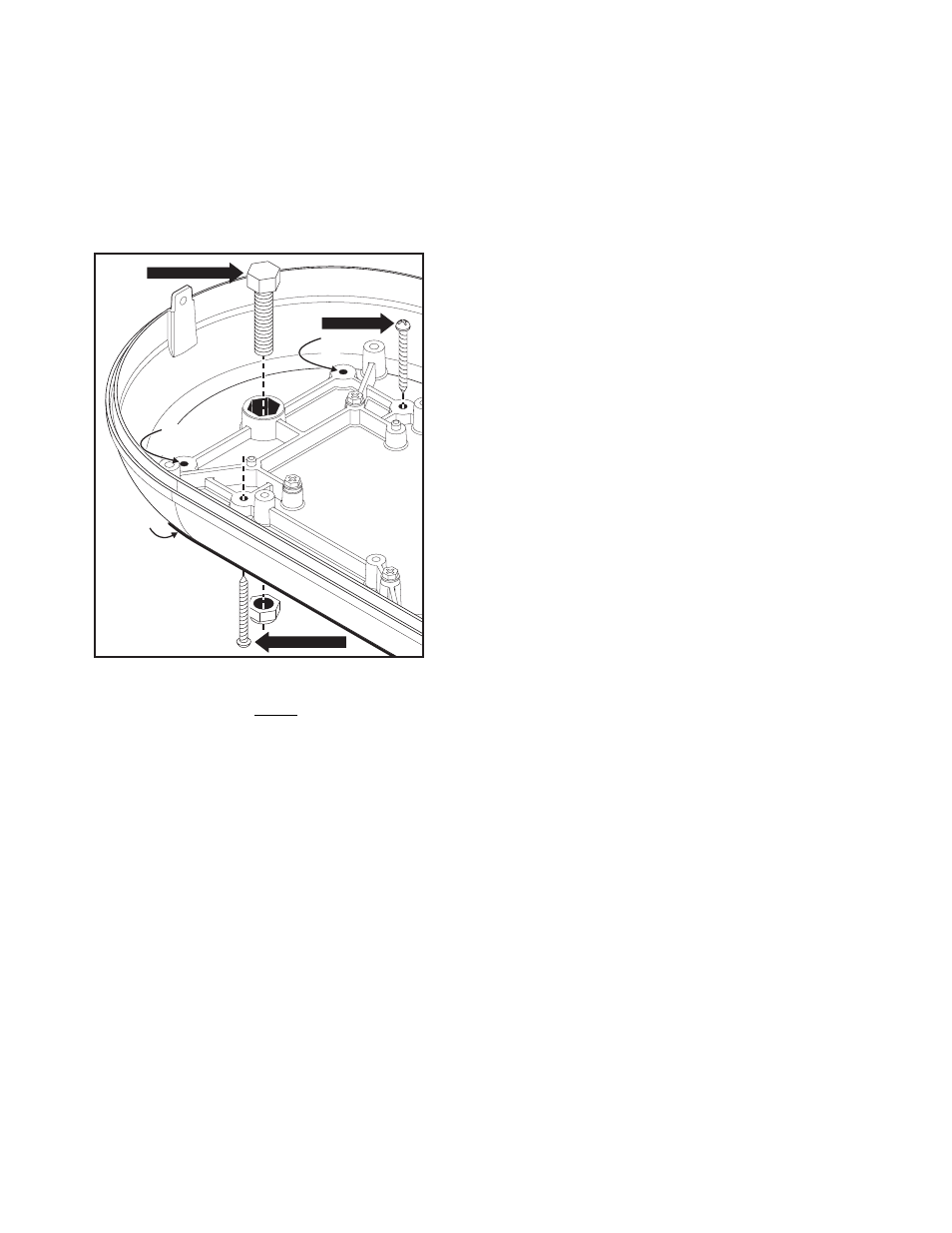
TOP MOUNTING
BOTTOM MOUNTING
CENTER MOUNTING
Optional
mounting
hole
Optional
mounting
hole
Gasket
WARNING! All customer supplied wires that connect to the positive
terminal of the battery must be sized to supply at least 125% of the
maximum operating current and FUSED at the battery to carry that
load. DO NOT USE CIRCUIT BREAKERS WITH THIS PRODUCT!
Top Mount:
1.
Remove the 2 screws at each end of the lightbar that secure the
dome to the base and remove the dome.
2.
With a 3/16” drill bit, drill out the 4 mounting bosses in the base for
clearance holes for #8 sheet metal screws (figs. 1 & 2).
3.
Be sure the mounting area is relatively flat. Using the lightbar base
as a template, scribe the 4 mounting hole locations onto the
mounting surface.
4.
Mark the location for a wire access hole behind the lightbar.
5.
Drill the mounting holes scribed in step 3 with a #29 drill bit and the
wire access hole from step 4 using a 3/8” drill bit.
6.
Install a 3/8” rubber grommet in the wire access hole and route the
wires through. Apply silicone sealing compound around the wires
and grommet.
7.
Carefully position the lightbar over the mounting holes and secure
the lightbar to the mounting surface using the #8 sheet metal screws
supplied.
8.
Replace the dome with the 2 screws removed in step 1.
9.
Wire the Guardian™ as shown in Fig. 3.
Fig. 1:
Lightbar Base