Fig. 5, Fig. 1, Strap mounting – Whelen FR8AAAA User Manual
Page 2: Fig. 2 fig. 3 fig. 4, Adjustable mounting foot model mkaj, Standard mounting foot model mkez
Page 2
Mounting
Foot
Tinnerman
Nut
Anchor
Plate
Locking
Plate
Mounting
Strap
Mounting Screw
Tension Bolt
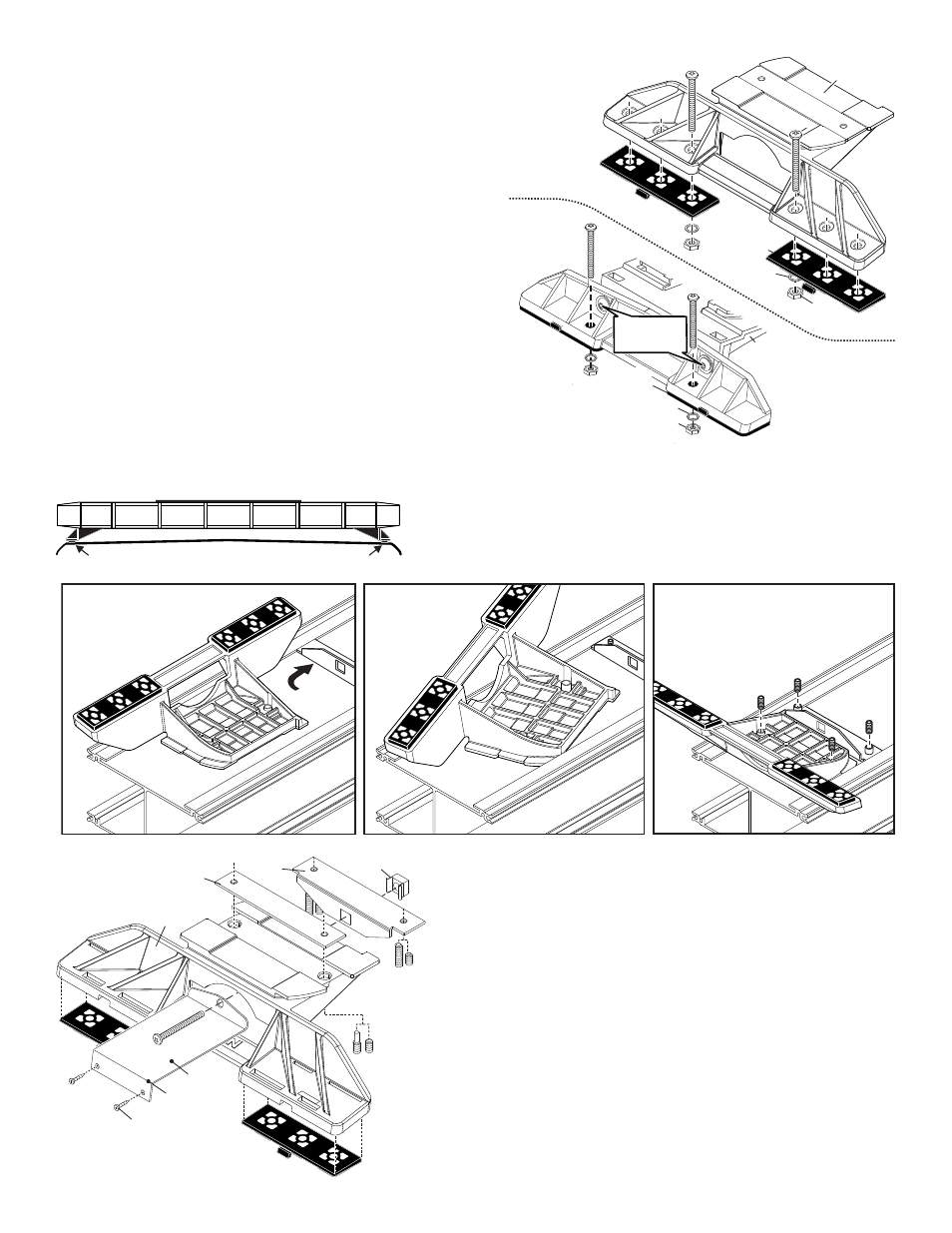
Fig. 5
Mounting
Pad
Adjustable
Mounting Foot
Model MKAJ
Washer
Nut
Bolt
Bolt
Bolt
Mounting
Plate
Mounting
Plate
Standard
Mounting
Foot
Model MKEZ
Fig. 1
Washer
Nut
TIGHTEN SCREWS
W I T H T O R Q U E
WRENCH SET AT
35 TO 40 IN/LBS
Mounting
Pad
IMPORTANT! The lightbar must be a minimum of 16” from radio
antennas!
Permanent Mounting:
1.
Locate the mounting foot and locking plate included with your lightbar. If not
already present, install the locking plate onto the mounting foot using the
supplied allen set screws (Fig. 1).
2.
Flip the lightbar upside-down to expose the bottom of the extrusion. Place the
mounting foot into the extrusion and rotate the foot so that the top of the foot
swings into position under the lips in the extrusion (Figs. 2, 3 & 4). NOTE: You
do not need the anchor plate shown in Figs. 2 - 4. This is used in strap
mounting.
3.
Repeat this procedure for the remaining mounting foot and return the lightbar
to its right side-up position.
4.
Position the lightbar onto the vehicle roof in the desired mounting location. One
often selected location is directly above the B-pillars. This area is the strongest
part of the roof. Check the light bar cable exit location to be sure that the
lightbar is facing the proper direction (Cable exits in rear).
5.
Adjust the mounting feet outwards so that they are as close to the edge of the
roof as possible (See below). When the mounting feet are properly positioned,
lightly tighten the allen head set screws.
6.
Turn the lightbar upside down and firmly tighten all of the mounting foot allen head set screws
(Fig.4). With the lightbar upside down, drill 2 holes into the mounting foot (for the mounting
bolts) using the holes in the mounting pads as guides, in the location shown in figure 1.
7.
Place the lightbar in its final mounting position on the vehicle, mark the mounting hole locations off onto
the mounting surface, remove the lightbar and drill the mounting holes. You will need to lower the vehicle
headliner (if present) for steps 7 & 8.
8.
Place the lightbar back onto the vehicle lined up with the mounting holes and secure the mounting feet to the vehicle using the supplied hardware.
Strap Mounting:
1.
Locate the mounting foot, anchor plate and locking plate. Loosely install the locking
plate onto the mounting foot using the allen set screws (Fig. 5).
2.
Flip the lightbar upside-down, install an anchor plate onto the extrusion and place a
mounting foot onto the extrusion (Fig. 2). Rotate the foot 90° counter-clockwise (Fig.
3) so that both sides slide under the lip in the extrusion.
3.
Repeat this procedure for the remaining mounting foot and return the lightbar to its
right side-up position.
4.
Position the lightbar on the vehicle roof and adjust the two mounting feet outwards
so that the mounting pads are resting near the edge of the roof. When properly positioned,
tighten the allen screws to hold them in place. Also slide the anchor plates up to the mounting
feet and tighten the allen screws securing the anchor plates.
5.
Insert the mounting strap onto the mounting foot (Fig. 5). Be sure that the strap fits flush
against the vehicle where it will be secured. Insert the tension bolt through the mounting strap
and into the anchor plate. Tighten slightly with a long-shafted, Phillips screwdriver. Repeat
procedure for other side of vehicle.
6.
Use the holes in the end of the strap as a template to drill the pilot holes for the sheet metal
screws through the strap and into the vehicle. Repeat for other side of vehicle.
7.
Screw the sheet metal screws into the holes you drilled in step 6 and tighten firmly. Repeat for
other side of the vehicle. Firmly tighten the tension bolt to secure the lightbar to the vehicle.
IMPORTANT: Unless otherwise specified, the lightbar mounting feet must be sitting
as close to the edge of the roof as possible. Mounting feet must also be in full
contact with the roof and not be hanging off the edge. For strap mounted bars, the
lightbar should be about the same width as the vehicle roof. If the lightbar is too
large or small it will not mount properly to the vehicle and may shift or come loose
during driving.
1/2" Minimum Clearance at Closest Point
Loosely secure foot and locking plate.
Insert foot into extrusion with
locking plate attached.
ANCHOR
PLATE
Twist foot
into position
Fig. 2
Fig. 3
Fig. 4