Control cable wire operation – Whelen FR8AAAA User Manual
Page 3
Page 3
IMPORTANT! When routing the wires, it is important to choose a
path that will keep the wires away from excessive heat or any vehicle
equipment that could compromise the integrity of the wires (ex.
trunk lids, door jams, etc.) Before returning the vehicle to service,
confirm the proper operation of this product, as well as all vehicle
components/equipment.
Control Cable Wire Operation:
Wht/Vio: Scan-Lock™
(Fuse wire @ 1 AMP)
To change the flash pattern on any option, activate only that option.
TO CHANGE PATTERNS: To cycle forward to the next available pattern
apply +VBAT to the WHITE-VIOLET wire for less than 1 second and
release. To cycle back to the previous pattern apply +VBAT to the WHITE-
VIOLET wire for more than 1 second and release.
TO CHANGE THE DEFAULT PATTERN: When the desired pattern is
displayed, allow it to run for more than 5 seconds. The lighthead will now
display this pattern when initially activated.
TO RESTORE THE FACTORY DEFAULT PATTERN: Turn power to the
lighthead off. While applying +VBAT to the WHITE-VIOLET wire, turn
power to the lighthead on. The factory default pattern is now displayed.
Use a Normally Open Momentary Switch for Scan-Lock™ operation.
Orange: Cruise
(Fuse wire @ 7.5 AMPS)
Applying +VBAT to the ORG wire activates all four corner rotators at low
intensity with no flash. Choose from 4 light intensities using Scan-Lock™.
Violet: Low Power
(Fuse wire @ 1 AMP)
Switch type is dependant on how the operator wishes Hi/Low to function:
Latching Mode: Apply +VBAT to the VIO wire for less than 1 sec., the
power supply is “latched” into low power. The unit must be turned off and
then back on to restore normal operation. (Momentary switch)
Level Mode: Apply +VBAT to the VIO wire for over 1 sec. The power
supply stays in low power mode until voltage is removed. (Toggle Switch)
Wht/Brn: Corner Rotators
(Fuse wire @ 15 AMPS)
Applying +VBAT to the WHT/BRN wire activates Corner Rotators.
the
Wht/Red: LED Rotator Option #1
(Fuse wire @ 7.5 AMPS)
Applying +VBAT to the WHT/RED wire activates Option #1.
I
nboard
Wht/Org: LED Rotator Option #2
(Fuse wire @ 7.5 AMPS)
Applying +VBAT to the WHT/ORG wire activates Option #2.
Wht/Yel: LED Rotator Option #3
(Fuse wire @ 7.5 AMPS)
Applying +VBAT to the WHT/YEL wire activates Option #2.
White: Driver Side Alley Light
(Fuse wire @ 3 AMPS)
Applying +VBAT to the WHT wire activates Driver Side Alley.
Yellow: Passenger Side Alley Light
(Fuse wire @ 3 AMPS)
Applying +VBAT to the YEL wire activates Passenger Side Alley
Wht/Blk: Take Downs
(Fuse wire @ 5 AMPS)
Applying +VBAT to the WHT/BLK wire activates Take Downs.
Green: Front Flashers
(Fuse wire @ 7.5 AMPS)
Applying +VBAT to the GREEN wire activates Front Flashers.
Blue: Rear Flashers
(Fuse wire @ 7.5 AMPS)
Applying +VBAT to the BLUE wire activates Rear Flashers.
NOTE: Rotator Options #1, #2 and #3 can run up to two rotators each.
WARNING! All customer supplied wires that connect to the positive
terminal of the battery must be sized to supply at least 125% of the
maximum operating current and FUSED at the battery to carry that
load. DO NOT USE CIRCUIT BREAKERS WITH THIS PRODUCT!
Ground Cable:
Black: Ground Wire / Extend to ground.
ROTATOR
(clockwise shown)
ROTATOR counterclockwise starts on the opposite side and travels in the opposite direction.
ROTATOR flash patterns operate as shown. You can change the pattern speed and direction (75 or 150 FPM) (clockwise or counterclockwise).
In patterns 9 - 14 each LED panel will flash in ModuFlash, DoubleFlash or QuadFlash.
WIGWAG flash patterns operate as shown. The difference in available
flash patterns is the speed
WIGWAG
the pattern cycles (75 or 150 FPM).
is the same except after each sweep there is a delay before the pattern sweeps back simulating the light going around a full beacon.
Center WIGWAG
1
STARTS
H E R E
2
STARTS
H E R E
3
STARTS
H E R E
2
STARTS
H E R E
WIGWAG
1
STARTS
H E R E
3
STARTS
H E R E
Rotator
Rotator 75
Rotator 150
Rotator 150
WigWag 75
WigWag 150
Center WigWag 75
Center WigWag 150
Rotator ModuFlash™
Rotator ModuFlash™
75
PATTERN
#
DIRECTION
Counter Clockwise
Clockwise
Counter Clockwise
Clockwise
N/A
N/A
N/A
N/A
Counter Clockwise
Clockwise
1.
2.
3.
4.
5.
6.
7.
8.
9.
10.
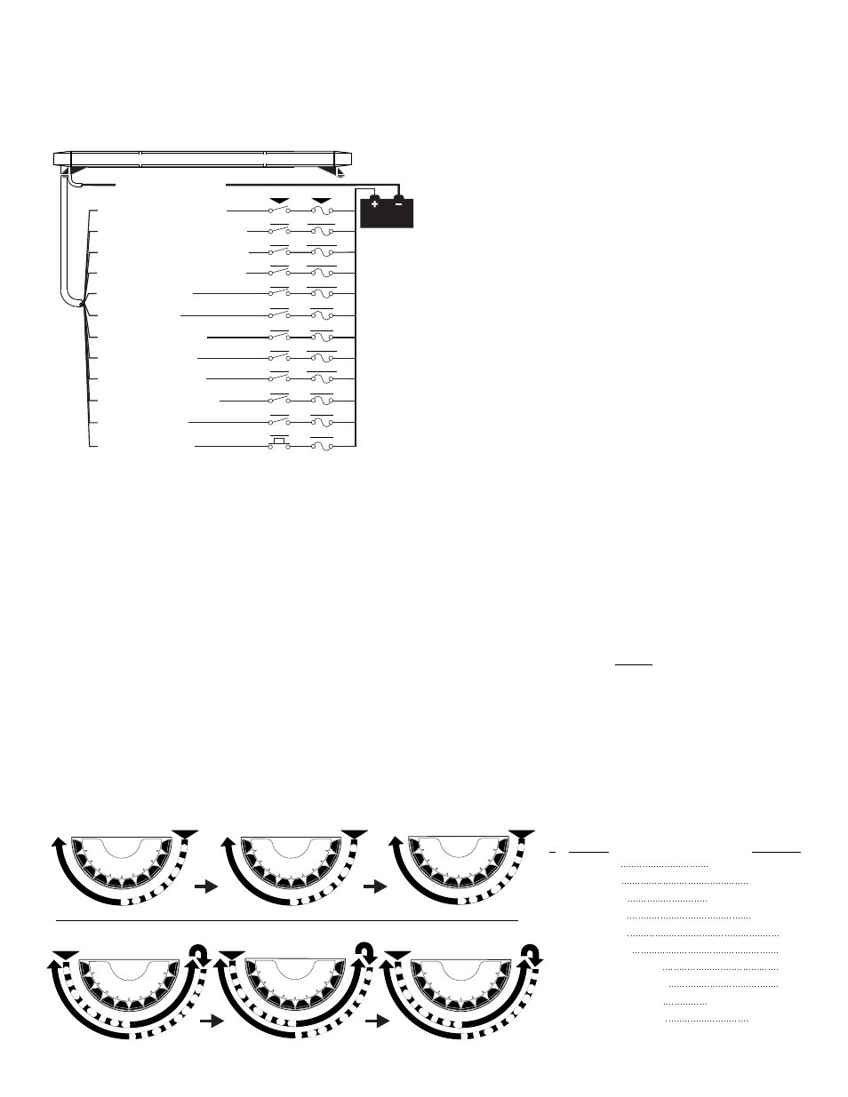
Flash Patterns:
WHT/BRN - Corner Rotators
WHT/RED - LED Rotator Option 1
WHT/ORG - LED Rotator Option 2
WHT/YEL - LED Rotator Option 3
VIOLET - Low Power
GREEN - Front Flashers
BLUE - Rear Flashers
WHT/BLK - Take Downs
YELLOW - Passenger Alley
WHITE - Driver Alley
8 GA.
- (-) GROUND
BLACK
All fuses &
s w i t c h e s
customer
supplied
BATTERY
FUSE
SP/ST
7.5 AMP
SP/ST
SWITCH
15 AMP
SP/ST
7.5 AMP
SP/ST
7.5 AMP
SP/ST
1 AMP
SP/ST
7.5 AMP
SP/ST
7.5 AMP
SP/ST
5 AMP
SP/ST
3 AMP
SP/ST
3 AMP
WHT/VIO - ScanLock
Freedom™ Rota-Beam™ Lightbar
ORANGE - Cruise
SP/ST
1 AMP