Permanent mounting, Routing the lightbar cable(s), Connecting the power cable – Whelen IB8JJJJ User Manual
Page 3: Connecting the communication cable, Troubleshooting
Page 3
Routing the Lightbar Cable(s):
1.
To protect the headliner from damage caused by drilling the cable access hole
through the vehicle roof, allow a 5” to 7” distance between roof and headliner
by lowering the headliner before drilling.
2.
Using a 1” hole saw, drill the cable access hole then use a round file to smooth
and de-burr the edges of the hole. Install a 1” grommet (user supplied).
NOTE: There may be a roof support member that spans the distance between
the driver’s and passenger’s side. DO NOT DRILL THROUGH THIS MEMBER!
Adjust the location until the hole can be drilled without contacting this support
member.
3.
Insert the cable(s) through the cable access hole into the vehicle. Use RTV
silicone to weatherproof the access hole after the cable(s) are pulled
completely into the vehicle.
4.
Route the cable(s) one at a time to their respective destinations (power cable to
vehicle battery; control cable to switch panel). Refer to the instructions included
with your switches for switch wiring information.
IMPORTANT AIR BAG WARNING!Refer to front cover for necessary air bag
precautions.
Connecting the Power Cable:
WARNING! All customer supplied wires that connect to the positive terminal
of the battery must be sized to supply at least 125% of the maximum operating
current and FUSED at the battery to carry that load. DO NOT USE CIRCUIT
BREAKERS WITH THIS PRODUCT!
1.
Follow the factory wiring harness through the firewall. It may be necessary to
drill a hole in the firewall. If so, be absolutely sure that there are no components
that could be damaged by drilling. After the hole has been drilled, insert a
grommet to protect the cable.
2.
Route the cable along the factory wiring harness towards the battery. Install a
50 amp fuse block (customer supplied) on the end of the RED wire in the power
cable. NOTE: Remove the fuse from the fuse block before connecting any
wires to the battery.
3.
Connect the BLACK wire to Chassis Ground.
Connecting the Communication Cable:
Splice the GREEN and GREY wires from the lightbar to the GREEN and GREY wires
from the Controller.
Troubleshooting:
Your lightbar should now be fully operational. If it is not functioning properly, check
your connections for the following:
•
The positive wire (RED) is properly connected to the battery, by way of
the user supplied fuse block.
•
A working 50 amp fuse is installed in the fuse block.
•
The ground wire (BLACK) is properly connected to the factory ground. Be
sure that the wire is fully grounded to this location.
•
The two communication wires (GREEN and GREY) are properly
connected to their communication designations.
Refer to your controller instructions for connections and operation.
IMPORTANT! It is the responsibility of the installation technician to make sure
that the installation and operation of this product will not interfere with or
compromise the operation or efficiency of any vehicle equipment!
CAUTION! DO NOT LOOK DIRECTLY AT THESE LED’S WHILE THEY ARE ON.
MOMENTARY BLINDNESS AND/OR EYE DAMAGE COULD RESULT!
I M P O R TA N T W A R N I N G !
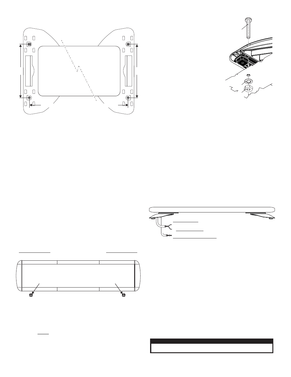
6½"
Measure distance on lightbar being mounted
6½"
Permanent Mounting:
Caution:
Permanent mounting of this product will require drilling.
It is absolutely necessary to make sure that no other vehicle
components could be damaged by this process. Check both sides of
the mounting surface before starting. If damage is likely, select a
different mounting location.
1.
Install the mounting foot to the lightbar following steps 1 thru 4 of
“Strap Mounting”.
2.
Position the lightbar onto the
vehicle in its exact mounting
location and mark the location
of the mounting holes onto the
mounting surface using the
mounting feet as templates.
If the permanent mounting
holes in the mounting feet are
difficult to access, you can use
the measurements shown here
to mark off and drill the
mounting holes. You will also
need to measure the distance
between the mounting feet for
your application since lightbar
width will depend on the
lightbar you are mounting.
3.
Remove the lightbar and drill
the 4 mounting holes.
4.
Install the lightbar using the supplied 1/4 - 20 Phillips Pan Head Metal
Screw, 1/4” Internal Tooth Lock Washer and 1/4 - 20 X 7/16 Hex Nut.
IMPORTANT! It is the responsibility of the installation technician to
make sure that the installation and operation of this product will not
interfere with or compromise the operation or efficiency of any
vehicle equipment! Before returning the vehicle to active service,
visually confirm the proper operation of this product, as well as all
vehicle components/equipment.
Drilling the Cable Access Hole
FRONT OF LIGHTBAR
For
cables exiting
the Driver-side
of the extrusion
lightbars
with
For
cables exiting
the Passenger-side
of the extrusion
lightbars
with
POWER CABLE
2.
BLACK Wire
CHASSIS GROUND:
COMMUNICATIONS CABLE
2.
GREY / CAN L
1.
GREEN / CAN H
1. +12VDC
/ RED Wire / Requires a 50 AMP fuse, customer supplied.
PERMANENT
M O U N T I N G
MOUNTING
S U R FA C E
1/4 - 20 X 2-1/2"
PHILLIPS PAN HEAD
METAL SCREW
1/4"
INTERNAL TOOTH
LOCK WASHER
1/4 - 20 X 7/16
HEX NUT