5" mounting foot, Lightbar cables, 6 conductor option cable – Whelen JC4AAAA User Manual
Page 3: Conductor option cable
Page 3
Tinnerman
Plate
Locking
Plate
Mounting
Plate
Mounting
Foot
Nut
Mounting
Pad
Adjustment
screws
Lock
Washer
Mounting
Foot
Mounting
Pad
Tinnerman
Plate
Mounting
Strap
Mounting
Screw
Tension
Bolt
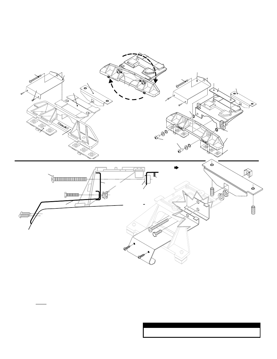
Adjustable Mounting Foot / Model MKAJ
Standard Mounting Foot / Model MKEZ
Tighten
screws
with
torque
wrench
set
at 35
to 40
in/lbs
Mounting
Strap
Mounting
Screw
Tension
Bolt
CAUTION! DO NOT LOOK DIRECTLY AT THESE LEDS WHILE THEY ARE ON.
MOMENTARY BLINDNESS AND/OR EYE DAMAGE COULD RESULT!
IMPORTANT WARNING!
MOUNTING FOOT
TINNERMAN
NUT
FOOT
ANCHOR
PLATE
SET
SCREW
Plate slides into
lightbar extrusion
5" Mounting Foot
NUT
BOLT
SPLIT LOCK
WASHER
METAL SCREW
NOTE: The mounting straps are made to fit the contours of individual
vehicles. The strap
may look different.
shown here is for example only. The strap
for your vehicle
NOTE:
NOTE:
STRAP
S H E E T
M E T A L
SCREWS
EXTENSION
VEHICLE ROOF
8.
Open both drivers side doors. In the area directly below the mounting foot,
carefully pull the drivers side weather-strip away from the vehicle. Remove
enough so that the area where the mounting strap will be secured to the
vehicle is exposed. Repeat procedure for passenger side.
9.
Insert the mounting strap through the mounting foot. Be sure that the strap fits
flush against the area where it will be secured onto the vehicle. Insert the
tension bolt through the mounting strap and into the tinnerman nut on the
tinnerman plate. Tighten slightly with a long shafted, Phillips screwdriver.
Repeat procedure for passenger side.
10.
If your mounting strap has mounting holes in the end of the strap, use these
holes as a template to drill appropriately sized pilot holes through the strap and
into the vehicle. Repeat for passenger side of the vehicle.
11.
Firmly tighten the tension bolts to secure the lightbar to the vehicle.
NOTE: Model MKAJ is an adjustable mounting foot. On this model you may
loosen the screws on the rear of the foot and adjust the angle of the lightbar.
This feature can be used if the angle of the roof is not level with the road.
IMPORTANT: To adjust the leveling screws you must use a torque wrench set
at 35 to 40 in./lbs.
Lightbar Cables:
Standard Lightbar: This lightbar uses a 4-conductor cable for LEDs and a 6- and 3-
conductor cable for options. There is also an option for Brake-Tail to connect to your
brake lights. Extend the 3-, 4- and 6-conductor cables towards your switch panel.
The instructions included with your switches will provide switch wiring information.
The optional brake-tail cable connects to the brake lights.
Refer to the next page for wire designations and fusing
.
WARNING! All Customer supplied wires that connect to the positive terminal of
the battery must be sized to supply at least 125% of the maximum operating
current and FUSED at the battery to carry that load. DO NOT USE CIRCUIT
BREAKERS WITH THIS PRODUCT!
6 Conductor Option Cable:
WHITE:
Apply +12 volts to activate the Take-downs or Worklight
GREEN:
Apply +12 volts to activate the Passenger Side Alley lights
RED:
Apply +12 volts to activate the Driver Side Alley light.
BLUE:
Apply +12 volts to activate the Take-downs in flashing mode.
3-Conductor Option Cable:
RED: Scan-Lock™
LED’s must be on for Scan-Lock to work.
TO CHANGE PATTERNS: To cycle forward to
the next available pattern: Apply +12 volts to
the RED wire for less than 1 second and
release. To cycle back to the previous pattern:
Apply +12 volts to the RED wire for more than 1 second and release.
TO CHANGE THE DEFAULT PATTERN: When the desired pattern is active, allow it
to run for more than 5 seconds. The lighthead will now display this pattern when
activated.
TO RESTORE THE FACTORY DEFAULT PATTERN: With power to the lightheads
off, apply +12 volts to the RED wire. While still applying +12 volts to the RED wire,
turn power to the lightheads back on. The factory default pattern should now be
displayed.
A normally open momentary switch can be used to control Scan-Lock
operation.
Installation: If your lightbar has a 5” mounting foot, it will assemble
differently than the standard mounting foot. It also uses an
extension to compensate for the extra height. Follow these
illustrations for assembly. Mounting to the lightbar is the same.