Fig. 3, Fig. 2, Fig. 1 – Whelen MKLP81 User Manual
Page 2: Strap mounting
Page 2
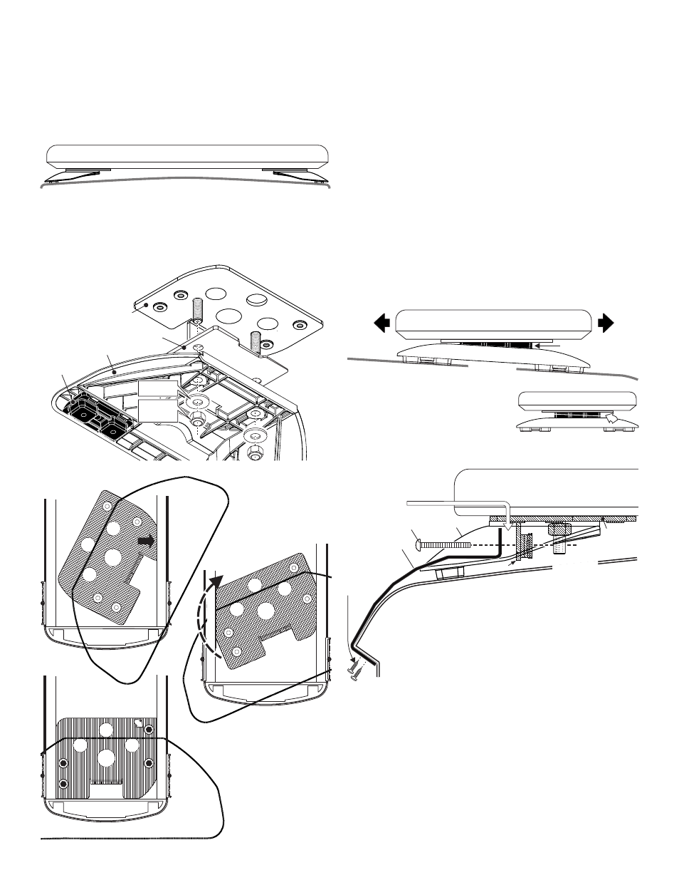
Fig. 3
#10 X 1/2"
Phillips Pan
Head Sheet
Metal
Screw
Tension Bolt
Mounting
Foot
Cage Nut
NOTE: With the strap in place on
the vehicle roof, there should be
3/8" distance (max) between the
end of the strap and the cage nut
(before tightening).
Mounting
Bracket
Mounting Strap
Edge of Roof
Roof Surface
front of
vehicle
SPACER
rear of
vehicle
Light must project straight out from front and rear
Be sure vehicle is parked on a level surface
VEHICLE ROOF
1/2" minimum clearance at closest point
Unless otherwise specified, lightbar mounting feet must be sitting as close to
the edge of the roof as possible and not be hanging off the edge.
IMPORTANT: For strap mounted lightbars, be sure you have the right sized bar
for your vehicle. The lightbar should be approximately the same width as the
vehicle roof. If too large or small it will not mount properly to the vehicle and
may come loose during driving.
FRONT VIEW
IMPORTANT! The lightbar must be a minimum of 16" from any radio
antennas.
IMPORTANT! This mounting foot can NOT be used on Freedom™
Centurion™ or Delta™ model lightbars.
NOTE: There may be a roof support member that spans the distance
between the driver’s and passengers side. DO NOT DRILL THROUGH
THIS MEMBER! Adjust the location until the holes can be drilled
without contacting this support member.
Strap Mounting:
1.
Install the mounting bracket to the mounting foot using the supplied
5/16 FLAT WASHERS and 5/16 - 18 ELASTIC STOP NUTS (Fig. 1).
Do NOT install the optional spacers yet.
2.
Place the bracket into the track on the bottom of the extruded base of
the lightbar and twist it into position (Fig. 2).
3.
Slide the bracket to the outer end of the base extrusion and secure
the bracket to the extrusion using the four 1/4 - 20 X 1/2 ALLEN SET
SCREWS (Fig. 2). Repeat steps 1 - 3 for other side of lightbar.
4.
Installing Spacers: Spacers are used as required to adjust the
lightbars clearance from the vehicle roof. Spacers are also used to
make the lightbar level with the road so that the light does not project
up or down when viewed from the front or rear of the vehicle. Each
spacer creates a 2° incline.
Lightbar angle: Place the lightbar onto the vehicle roof in its exact
mounting location and use a level to check the angle of the lightbar. If
(because of the curvature of the vehicle roof) the front and rear lights
project up or down, you will need to install one of the supplied spacers.
Note the angle of the tilt to determine where to place the spacer.
Installation: Remove the mounting feet (not the bracket) and install the
spacer (maximum 1 per side) then reinstall the feet.
Distance
from roof: The lightbar must be no
closer than 1/2 inch (at the closest point)
from the vehicle roof. Installation:
Remove the mounting feet (not the
bracket), install the spacers as shown
(maximum 2 per side) and reinstall feet.
5.
With the lightbar in position on the vehicle, slide the
end of the mounting strap (with the single hole) into the
mounting foot as shown and loosely secure it to the
foot with the tension bolt (Fig. 3).
NOTE: When the opposite end of the strap (which
mounts to the vehicle) is in its mounting position
(on the edge of the roof) the end of the strap going
to the foot should be no more than 3/8” from the
cage nut it mounts to. If the distance from the strap to the cage
nut is greater than 3/8”, remove the lightbar from the vehicle
and move both mounting feet the necessary distance to correct
this before doing step 5.
6.
Bring the outside of the mounting strap down to the edge of the
vehicle roof. The outer end of the strap should hook around the roof
(Fig. 3). Mounting straps are made for specific vehicles and the one
designed for your vehicle will conform to the edge of that roof.
7.
Make sure the strap is in position on the edge of the roof and the
other end lines up properly with the cage nut. Drill two holes for a #10
screw through the two mounting holes in the strap and secure the
strap with the two #10 X 1/2” PHILLIPS PAN HEAD SHEET METAL
SCREWS.
8.
Tighten the tension bolt firmly to secure the foot to the vehicle.
Stack 2 spacers face to face to
raise the height of the lightbar .
SIDE VIEW
Secure bracket with
allen set screws (QTY 4)
Fig. 2
Swing other side of bracket
under other lip
Insert round side of bracket under
lip in extrusion
MOUNTING
PAD
MOUNTING FOOT
2 DEGREE SPACER
MOUNTING
BRACKET
Fig. 1
5/16 FLAT
WASHER
5/16 - 18
E L A S T I C
STOP NUT